Method and apparatus for purifying polycrystalline silicon through rotation and blow induced inversion solidification

A technology of reverse solidification and polysilicon, applied in chemical instruments and methods, silicon compounds, inorganic chemistry, etc., can solve the problems of high cost of cutting equipment, affecting purification effect, unfavorable production cost, etc., to reduce energy consumption and process links , The effect of saving production cycle and cost

Inactive Publication Date: 2013-03-20
DALIAN UNIV OF TECH QINGDAO NEW ENERGY MATERIALS TECH RES INST CO LTD
View PDF6 Cites 13 Cited by
  • Summary
  • Abstract
  • Description
  • Claims
  • Application Information

AI Technical Summary

Problems solved by technology

[0003] However, at the end of the solidification of the ingot, impurities are enriched in the melt at the top of the crucible. During the final slow solidification process, the parts with high impurity content will diffuse to the parts with low impurity content, so that the purity of silicon will gradually increase with the prolongation of the holding time. Reduced, which affects the purification effect, and in this case, the tail waste removed is as high as 25%~35%, that is, the yield is only 65-75%, and the

Method used


Image

  • Method and apparatus for purifying polycrystalline silicon through rotation and blow induced inversion solidification

Examples


Embodiment 1

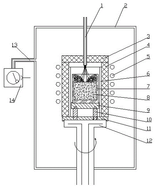
[0023] Such as figure 1 The equipment used in the method of rotating and blowing induced reverse solidification to purify polysilicon, the outer wall is composed of a vacuum chamber 2, and a vacuum pipeline 13 is installed on the outer wall, and one end of the vacuum pipeline 13 is connected with a vacuum pump group 14 for The vacuum chamber is evacuated, and the water cooling plate 12 is movable and sealed at the bottom of the vacuum chamber 2, and a cooling water pipeline is installed inside to realize the cooling of the water cooling plate. The graphite plate 11 is placed on the top of the water cooling plate, and the graphite plate 11 is provided with a One end of the graphite pillar 10 is nested and connected with the graphite plate 11 through the hole, and the other end is nested and connected with the graphite tray 9. The crucible 7 is placed on the graphite tray 9, and the graphite heating element 6 is set on the periphery of the crucible and fixed in the vacuum chamber...

Embodiment 2

[0029] The equipment described in Example 1 is used to induce reverse solidification to purify polysilicon. First, add the cleaned silicon material of 95% of the crucible volume to the crucible 7, with a purity of 99.5%. Vacuum to 5Pa;

[0030] The second step of smelting and solidification: turn on the power, use the induction coil 5 and the graphite heating element 6 to heat the silicon material in the crucible 7 to 1450 ° C until it is completely melted into a silicon melt, keep it at this temperature for 30 minutes, and pull it vertically downward The water cooling plate 12 makes the silicon melt in the crucible 7 move vertically downward at a constant speed at a speed of 2 mm / min to pull the ingot. The silicon melt is directional solidified from the bottom of the crucible 7 to the top. When the silicon melt is solidified to 80%, Rotate the water-cooled plate 12 to rotate the crucible 7 at a rate of 30 r / min, so that the upper layer of the remaining silicon melt gathers to...

Embodiment 3

[0033] The equipment described in Example 1 is used to induce reverse solidification to purify polysilicon. First, add the cleaned silicon material with a crucible volume of 93% to the crucible 7, with a purity of 99.7%. Vacuum to 2Pa;

[0034]The second step of smelting and solidification: turn on the power, use the induction coil 5 and the graphite heating element 6 to heat the silicon material in the crucible 7 to 1500 ° C until it is completely melted into a silicon melt, and keep it at this temperature for 45 minutes, and pull it vertically downward The water cooling plate 12 makes the silicon melt in the crucible 7 move vertically downward at a constant speed at a speed of 0.8 mm / min to pull the ingot. The silicon melt is directional solidified from the bottom of the crucible 7 to the top. When the silicon melt solidifies to 85% , rotate the water cooling plate 12 to make the crucible 7 rotate at a rate of 40r / min, so that the remaining silicon melt in the upper layer ga...


PUM


Abstract

The invention belongs to the technical field of metallurgical purification, and especially relates to a method and an apparatus of induced inversion solidification. The method comprises the following steps of: in the vacuum environment, heating the cleaned silicon material until the silicon material is completely melted and directionally solidified; when 80-90% of solidification is completed, rotating the crucible so that the silicon melt of the upper layer is gathered towards the sidewalls of the crucible under the action of the centrifugal force, and simultaneously blowing an inert gas to the center of the top of the left silicon melt of the upper layer so that the left silicon melt of the upper layer is gathered towards the sidewalls from the center of the crucible under the action of the gas flow and quickly solidified inversely, and is completely solidified at the sidewalls of the crucible; after the whole silicon ingot is cooled, removing the cast ingot of the upper layer obtained through solidification on the sidewalls of the crucible, so as to obtain the left cast ingot as the high-purity silicon cast ingot. The apparatus provided by the invention is added with the functions of crucible rotation and blowing on the basis of the previous solidification apparatus. The method and the apparatus provided by the invention have the advantages that back-diffusion of impurities is reduced, the yield of the cast ingot is improved, the process links are reduced and the energy consumption is reduced; the equipment is convenient to reform and mount; the impurities enriched at the tail part of the cast ingot are effectively removed; and the production cycle and the production cost are saved.

Description

technical field [0001] The invention belongs to the technical field of metallurgical purification, in particular to a method for inducing reverse solidification to purify polysilicon, and also to its equipment. Background technique [0002] The development of the solar photovoltaic industry relies on the purification of silicon raw materials. In the process of purifying silicon raw materials, the directional solidification method is very important for removing metal impurities with very small segregation coefficients in silicon raw materials. One of the most effective methods, moreover, the directional solidification technique is widely used in metallurgical purification. Directional solidification is the use of forced means to form a temperature gradient in a specific direction in the melt, so that the melt at the low temperature part crystallizes and nucleates, and becomes the starting point for the solidification of the melt. Solidify in the opposite direction to obt...

Claims


Application Information

Patent Timeline
IPC IPC(8): C01B33/037
Inventor 姜大川安广野石爽谭毅
Owner DALIAN UNIV OF TECH QINGDAO NEW ENERGY MATERIALS TECH RES INST CO LTD
Why Eureka
Try Eureka