Layered pulse pressure-charging plug removal device and method for oil filed water injection well

A technology of pulse pressurization and oilfield water injection. It is applied in earth-moving drilling, wellbore/well components, and production fluids. Pressure adjustable effect

Active Publication Date: 2013-03-20
PETROCHINA CO LTD
View PDF10 Cites 16 Cited by
  • Summary
  • Abstract
  • Description
  • Claims
  • Application Information

AI Technical Summary

Problems solved by technology

[0004] Existing technology 1: Automatic booster pump for oil field water injection, application number is 01140026.9, this technology introduces a booster pump for water injection wells, because it needs a low-pressure water injection network as an auxiliary, its implementation will inject a large amount of low-pressure water into the low-pressure well required water, causing turmoil in the water injection system, making it difficult to achieve
[0005] Existing technology 2: a pressure regulating water injection pump, the application number is 96249259.0, the principle and disadvantages are basically the same as the above patents, and it is difficult to implement
[0006] Prior art 3: Oilfield water injection pressurized water wheel pump, application number 96228470.X; prior art 4: in-well pressurized water injection method and its device, application number 89100282.0; prior art 5: pressure pulse oil well water injection device , the application number is 200610005334.3; prior art 6: supercharged water injection device, the application number is 201010114436.5; the above prior art 3-6, all need to add a power device to realize the injection well injection, the process is complicated and the cost is high

Method used


Image

  • Layered pulse pressure-charging plug removal device and method for oil filed water injection well

Examples


Embodiment Construction

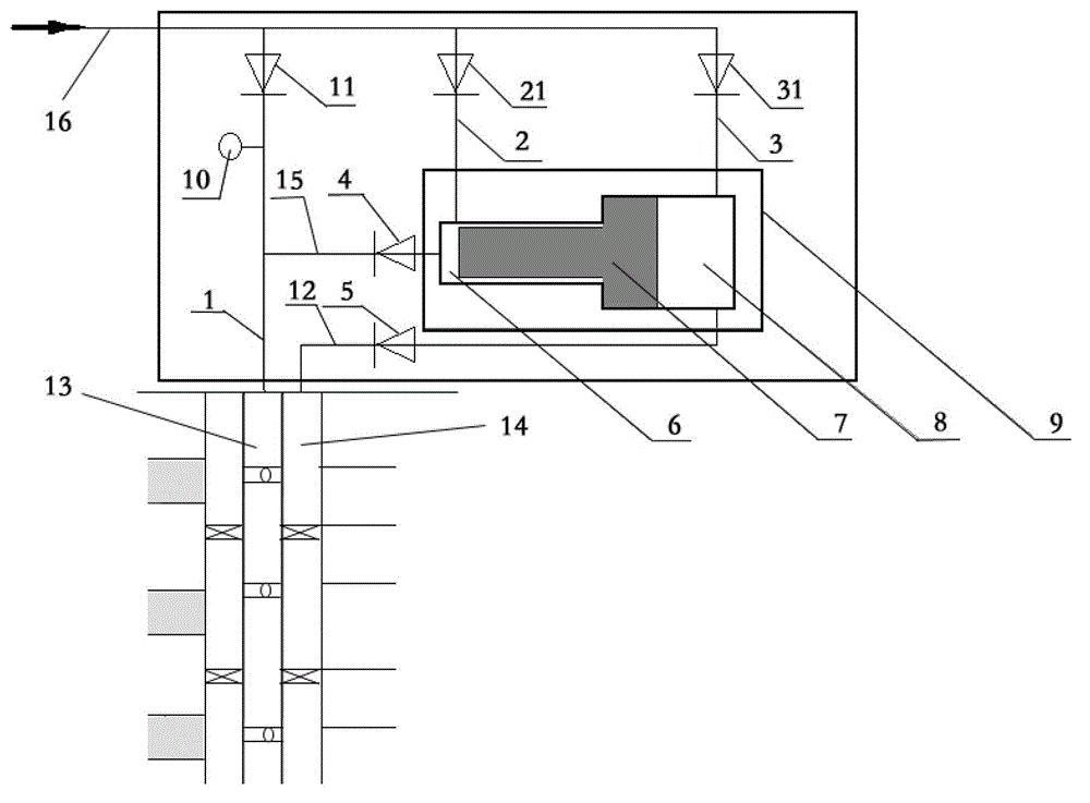
[0046] The layered pulse pressurizing and plugging removal device for oilfield water injection wells of the present invention is installed on the water injection trunk line, high pressure water injection pipeline and water injection well; the first end of the high pressure injection pipeline is connected with a water injection trunk line, and the second end is connected with The oil pipe valve of a water injection well is connected; the layered pulse pressurization and blockage removal device of the oil field water injection well includes: a pressurization tank and a low pressure injection pipeline; the pressurization tank is provided with a high pressure cavity and a low pressure cavity, the high pressure cavity and Pistons are arranged between the low-pressure chambers, and they are respectively connected to the water injection trunk via a first water inlet pipeline and a second water inlet pipeline; the high-pressure chamber communicates with the high-pressure injection pipeli...


PUM


Abstract

The invention discloses a layered pulse pressure-charging plug removal device and method for an oil filed water injection well. The device is arranged onto a water injection main line, a high-pressure water injection pipeline and the water injection well. The device comprises pressure-charging boxes, a low-pressure water injection pipeline and a high-pressure water injection pipeline, wherein the pressure-charging boxes are respectively provided with a high-pressure chamber and a low-pressure chamber; a piston is arranged between the corresponding high-pressure chamber and the corresponding low-pressure chamber, and the high-pressure chamber and the low-pressure chamber are communicated with the water injection main line respectively through a first water inlet pipeline and a second water inlet pipeline; the high-pressure chambers are communicated with the high-pressure water injection pipeline through a high-pressure pipeline, and are communicated with the water injection well; the first end of the low-pressure water injection pipeline is communicated with the low-pressure chambers; the second end of the low-pressure water injection pipeline is connected with a sleeve valve of the water injection well; the high-pressure water injection pipeline, the first water inlet pipeline, the second water inlet pipeline, the high-pressure pipeline and the low-pressure water injection pipeline are respectively provided with a first retaining valve, a second retaining valve, a third retaining valve, a fourth retaining valve and a fifth retaining valve in sequence; and a pressure gage is arranged between the first retaining valve and an oil pipe valve. Pressure-charging plug removal treatment can be independently performed on a low water intake layer in the water injection well so as to improve a water injection profile.

Description

Technical field [0001] The invention relates to a pulse pressurization and plugging removal technology for small layers of oilfield water injection wells, in particular to an oilfield water injection well stratification that performs pressurization and plugging removal treatment on a low water absorption layer in a separate water injection well to improve the water absorption profile Pulse pressurization and blocking removal device and method thereof. Background technique [0002] Block Jin 16 in Jinzhou Oil Production Plant of Liaohe Oilfield accounted for 30.4% of the perforated section in 2003 without water absorption, and rose to 53.6% in 2009. Block Jin 99 accounted for 34.1% in 2003, and it rose to 54.3% in 2009. In order to increase the thickness of the water-absorbing layer, it is necessary to increase the water absorption of the low-permeability layer. Three methods can be used to plug the high-permeability layer (injection well profile control), pressurized water inject...

Claims


Application Information

Patent Timeline
Patent Type & Authority Applications(China)
IPC IPC(8): E21B31/00E21B43/20
Inventor 高玉军
Owner PETROCHINA CO LTD
Why Eureka
Try Eureka