
System and method for operation control of vehicle-mounted drill machine

A control system and technology for drilling rigs, which are applied to the automatic control system of drilling, drilling equipment and methods, drilling equipment, etc., can solve the problems of operation safety impact, vehicle movement, complicated control methods, etc., and improve operation safety. , to avoid the effect of vehicle swaying

Active Publication Date: 2013-03-20
XUZHOU HEAVY MASCH CO LTD
View PDF6 Cites 12 Cited by
  • Summary
  • Abstract
  • Description
  • Claims
  • Application Information

AI Technical Summary

Problems solved by technology

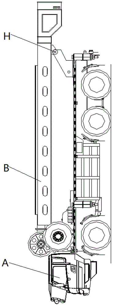
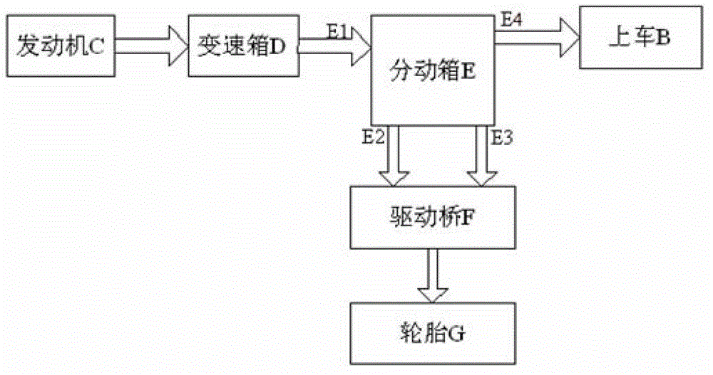
[0008] However, when the vehicle-mounted drilling rig performs on-board switching operations during driving, that is, when the power take-off switch is pressed and the transfer case E is placed in the neutral state, the power of the engine C cannot be transferred from the output of the transfer case E immediately. Port E4 is switched to boarding B, which will cause dangerous situations such as vehicle movement, and the safety of operation will be seriously affected
[0009] In addition, the power take-off solenoid valve of the transfer case and the neutral solenoid valve of the transfer case of the current vehicle-mounted drilling rig are controlled by their respective switches, and the control method is relatively complicated.

Method used


Image

  • System and method for operation control of vehicle-mounted drill machine
  • System and method for operation control of vehicle-mounted drill machine
  • System and method for operation control of vehicle-mounted drill machine

Examples


Embodiment Construction

[0037] The technical solutions of the present invention will be described in further detail below with reference to the accompanying drawings and embodiments.

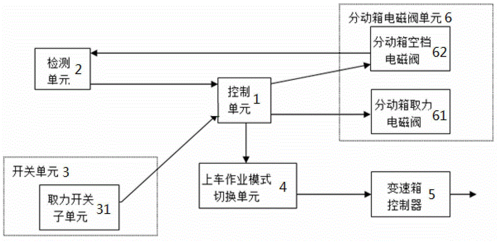
[0038] image 3 It is a schematic diagram of the principle of the first embodiment of the vehicle-mounted drilling rig operation control system provided by the present invention. Such as image 3 As shown, the vehicle-mounted drilling rig operation control system provided by the present invention includes a control unit 1, a detection unit 2, a switch unit 3, a boarding operation mode switching unit 4, a gearbox controller 5 and a transfer case solenoid valve unit 6, wherein:

[0039] Control unit 1 can adopt PLC (ProgrammableLogic Controller, programmable logic controller) well-known to those skilled in the art, and PLC can pass the signal such as input switching quantity, analog quantity through certain program design, according to established logical output control solenoid valve, Executive elements such as lights...


PUM


Abstract

The invention relates to a system and a method for operation control of a vehicle-mounted drill machine. The system comprises a control unit, a detection unit, a switch unit, a vehicle-mounted operation mode switching unit, a transmission box controller and a transfer case electromagnetic valve unit, wherein the switch unit comprises a power take off switch subunit; the transfer case electromagnetic valve unit comprises a transfer case power take off electromagnetic valve and a transfer case neutral position electromagnetic valve; the detection unit is used for detecting a braking state of the vehicle-mounted drill machine and a gear position state of a transfer case; when the vehicle-mounted drill machine is in a braking state, the power take off switch subunit sends out a power take off signal to the control unit, the transfer case power take off electromagnetic valve and the transfer case neutral position electromagnetic valve are electrified at the same time, and the transfer case is in the neutral position state at the moment; and a neutral position signal is sent to the control unit through the detection unit, the control unit generates a drive signal to be transmitted to the transmission box controller through the vehicle-mounted operation mode switching unit, and the transmission box controller switches an output mode into a vehicle-mounted operation mode. The system and the method, disclosed by the invention, can be used to improve the safety performance of the vehicle-mounted operation switching operation.

Description

technical field [0001] The invention relates to the field of engineering machinery, in particular to a vehicle-mounted drilling rig operation control system and method. Background technique [0002] With the high-speed and rapid economic growth, oil and natural gas resources are constantly depleted, and all countries are actively seeking new alternative energy sources. Energy strategy is a major strategy and a state-supported industry. my country's "Eleventh Five-Year Plan" outline also clearly pointed out: increase the exploration of oil and natural gas resources, focus on the exploration and exploration of unconventional oil and gas resources such as oil shale, and promote the diversification of oil and gas exploration and development subjects. In the implementation of the national energy strategy, the modernization level of drilling equipment has become an important factor. The vehicle-mounted drilling rig has the characteristics of lightness, flexibility, high efficienc...

Claims


Application Information

Patent Timeline
Patent Type & Authority Applications(China)
IPC IPC(8): E21B44/00E21B7/02
Inventor 王建东於磊吴高腾徐俊秒朱天罡
Owner XUZHOU HEAVY MASCH CO LTD
Learn More