Expansion flexible pipe joint

A flexible pipe and pipe shaft technology, applied in the direction of pipe/pipe joint/pipe fitting, adjustable connection, passing element, etc., can solve the problems of poor fixing operation, cutting workability, etc., and achieve good workability and reliable coating treatment. Effect

Active Publication Date: 2013-03-20
TOZEN CORP
View PDF9 Cites 8 Cited by
  • Summary
  • Abstract
  • Description
  • Claims
  • Application Information

AI Technical Summary

Problems solved by technology

[0006] Therefore, the object of the present invention is to solve the problems of the above-mentioned conventional pipe joints, to provide a fixing operation for removing the conventional stop ring which is poor in workability, and to prevent the occurrence of gaps without rusting, and to provide reliable coating treatment. , and can also easily respond to product length and / or deflection amount

Method used


Image

  • Expansion flexible pipe joint
  • Expansion flexible pipe joint
  • Expansion flexible pipe joint

Examples


no. 1 Embodiment approach

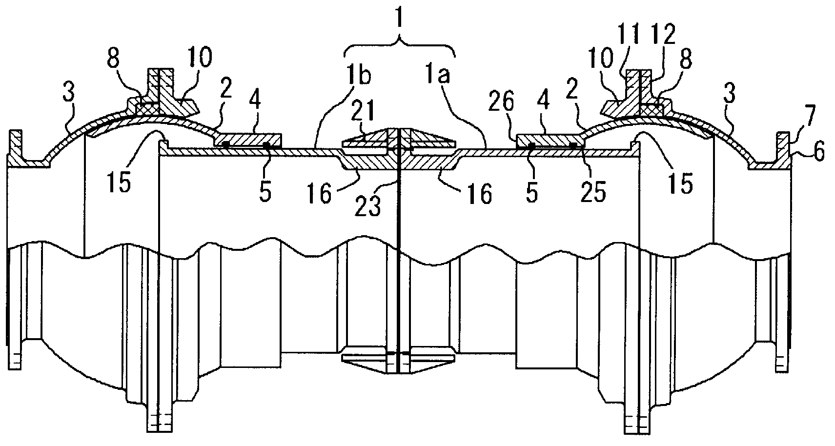
[0041] figure 1 It is a broken front view of the upper half of the telescopic flexible pipe joint. In this figure, 1 is a connecting pipe, which is composed of a pair of single pipes 1a and 1b. 2 and 2 are a pair of rotating spheres that are slidably fitted to both ends of the connecting pipe 1 in the direction of the tube axis, and a part of the outer peripheral surface is formed into a spherical surface, and 3 and 3 are inner peripheral surfaces arranged so as to become the same spherical surface. A pair of housings are in sliding contact with the outer peripheral surfaces of these rotating spheres 2 , 2 . On the other end of the rotating sphere 2,2 opposite to the housing 3,3, a short tubular sliding portion 4 extending in the axial direction is integrally provided, and the inner peripheral surface of the sliding portion and the outer peripheral surface of the connecting pipe 1 A plurality of O-rings 5 ​​are disposed between them so as to fit in, for example, annular groov...

no. 2 Embodiment approach

[0051] Figure 6 The second embodiment of the present invention is shown, and since this embodiment has the same parts as those of the first embodiment, the same reference numerals are assigned to such parts to omit description, and the different parts will be mainly described.

[0052] In the first embodiment, the single pipes 1a and 1b of the connection pipe 1 are connected to each other, but in the second embodiment, between the single pipe 1a and the single pipe 1b of the connection pipe 1, there are further connections between the single pipe 1a and the single pipe 1b on the outer peripheral surfaces of both ends. There is an extension tube 28 with a flange on it. If such an extension pipe 28 is connected and used by the above-mentioned flange, the length of the connection pipe 1 can be further adjusted appropriately, and there is an advantage that the amount of displacement can be further increased. Furthermore, since the bolt hole 20 with the stopper flange 18 is provi...


PUM


Abstract

The invention provides an expansion flexible pipe joint which eliminates existing baffle ring fixed operation whose operational performance is poor, restrains gaps and would not rust, and reliably performs coating processing. The expansion flexible pipe joint comprises a preset length connecting pipe, a pair of rotary spheres, and a pair of housings. The rotary spheres are relatively slidably embedded into two ends of the connecting pipe on a pipe axis direction in a manner of keeping water tightness, and a part of an outer peripheral surface forms a spherical surface. The housings form inner surfaces of the spherical surface whose outer peripheral surfaces are the same with outer peripheral surfaces of the rotary spheres, the inner surfaces are rotatably and slidably embedded in the outer peripheral surfaces of the rotary spheres in the manner of keeping water tightness. Anti-off blocking components are integrally disposed on an end of a rotary sphere side of the connecting pipe on the outer peripheral surfaces. Male threads and flanges with blocking components are disposed on the outer peripheral surfaces on the other end. A diameter of the male threads is larger than diameters of the rotary spheres. The flanges with the blocking components can be in thread joint with the male threads through female threads disposed on the inner surface, so that the expansion flexible pipe joint can be assembled and unassembled.

Description

technical field [0001] The present invention relates to a telescopic flexible joint, and in particular relates to connecting pipes such as water pipes and other connected pipes flexibly and flexibly so that no load in the bending direction will be applied to the buried piping even if the buried foundation changes due to earthquakes, etc. A technique that causes damage to buried piping, etc. Background technique [0002] Conventionally, as such a pipe joint, a pipe joint disclosed in Patent Document 1 has been known. As from claim 1 of the claims and figure 1 It is clearly stated in the description that it is a telescopic flexible pipe joint, which includes: a pair of shells that can be connected to the opposite ends of the pipe body, and a part of the inner peripheral surface is formed into a spherical shape; a pair of spherical rings inside each housing and capable of sliding while contacting the inner surface of the housing; a push ring fixed to the tip opening of each h...

Claims


Application Information

Patent Timeline
IPC IPC(8): F16L27/02F16L27/12
Inventor 徐永木
Owner TOZEN CORP
Why Eureka
Try Eureka