Shell for lighting device and lighting device with the same

A technology for lighting devices and shells, which is applied to cooling/heating devices of lighting devices, components of lighting devices, and damage prevention measures for lighting devices, etc., and can solve problems such as short circuit of LED light-emitting components, rust and corrosion of metal devices, etc. , to improve heat dissipation performance and reduce the number of parts

Inactive Publication Date: 2013-03-20
OSRAM GMBH
View PDF6 Cites 2 Cited by
  • Summary
  • Abstract
  • Description
  • Claims
  • Application Information

AI Technical Summary

Problems solved by technology

When the outside temperature is low, the moisture in the air in the assembly cavity may condense and accumulate on the transparent cover of the housing, affecting the

Method used


Image

  • Shell for lighting device and lighting device with the same
  • Shell for lighting device and lighting device with the same
  • Shell for lighting device and lighting device with the same

Examples


Embodiment Construction

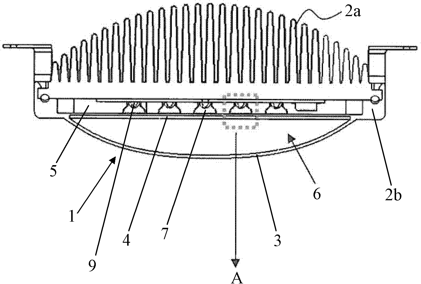
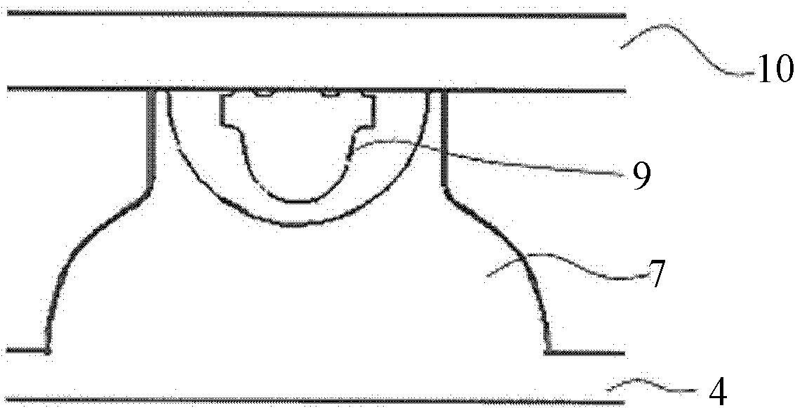
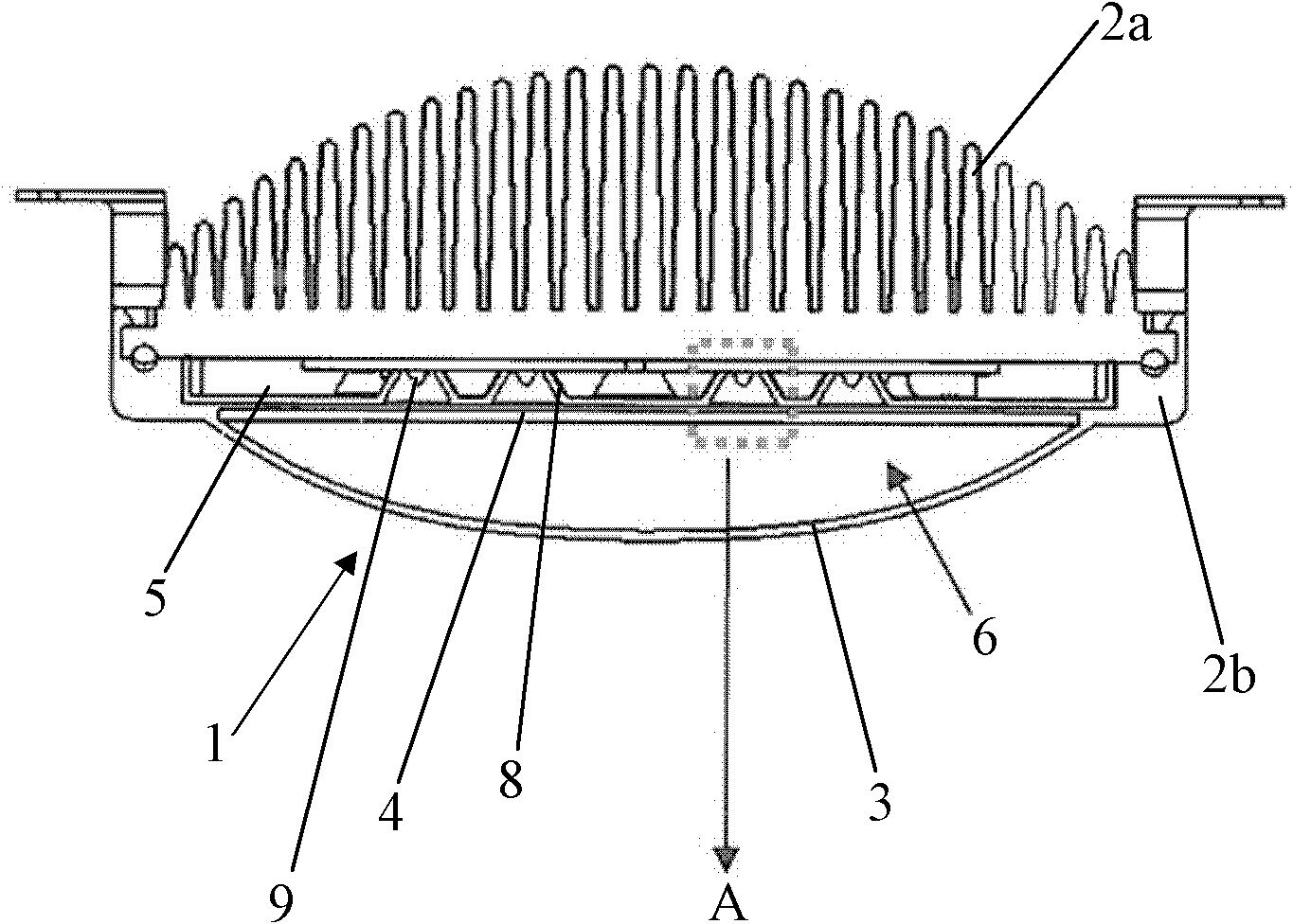
[0018] figure 1 A schematic view of a first embodiment of the housing according to the invention is shown. As can be seen from the figure, the housing 1 has two housing parts 2a, 2b, which are snapped together, wherein the housing part 2b is provided with a light-transmitting cover 3 and the housing The part 2a is designed as a heat sink, and the two housing parts 2a, 2b and the light-transmitting cover 3 jointly define a cavity. Further, it can be seen from the figure that a transparent partition 4 is arranged in the cavity, and the partition 4 separates the cavity into an assembly cavity 5 and an isolation cavity 6 which are sealed from each other, wherein a printed circuit board is arranged in the assembly cavity 5 10 and a plurality of light emitting components 9 and other devices installed on the printed circuit board 10. In this embodiment, the lighting device is designed as an LED lighting device, so LED chips, drivers and the like are arranged in the assembly cavity ...


PUM


Abstract

The invention relates to a shell (1) for a lighting device. The shell (1) for the lighting device comprises two shell bodies (2a, 2b) which are fastened with each other and a lamp shade (3), a cavity is limited by the two shell bodies (2a, 2b) and the lamp shade (3) together, wherein a transparent separator (4) is arranged inside the cavity to divide the cavity into an assemble cavity (5) and a segregate cavity (6) which are mutually sealed. The assemble cavity (5) is used for arranging a plurality of light emitting devices (9) for the lighting device and the segregate cavity (6) is limited by the lamp shade (3) and the separator (4) together. In addition, the invention further relates to a lighting device with the shell for the lighting device.

Description

technical field [0001] The invention relates to a casing for an illuminating device, which can prevent water vapor from condensing therein. Furthermore, the present invention also relates to a lighting device having the housing of the above type. Background technique [0002] Due to the characteristics of the environment in which it is used, the outdoor lighting device is usually equipped with a waterproof and dustproof casing. The light-emitting components of the lighting device, such as LED light-emitting components, are arranged in corresponding assembly cavities of the housing. Since the light-emitting components, especially the LED light-emitting components, generate a lot of heat during operation, the temperature in the assembly cavity will be relatively high. When the outside temperature is low, the moisture in the air in the assembly cavity may condense, thus gathering on the transparent cover of the casing, affecting the output of light. What's more, the condense...

Claims


Application Information

Patent Timeline
IPC IPC(8): F21V31/00F21V15/06F21V29/00F21S2/00F21V29/15
CPCF21V15/06F21V31/005F21V5/04F21V3/0418F21Y2101/02F21V3/02F21V13/02F21V15/011F21V15/01F21V29/22F21V13/04F21V3/0436F21V29/15F21V29/507F21V29/70F21Y2115/10F21V3/061F21V3/062
Inventor 冯耀军何源源袁海平李爱爱
Owner OSRAM GMBH
Why Eureka
Try Eureka