
Minitype airflow type gyro

An airflow type and gyroscopic technology, which is applied to steering sensing equipment and other directions, can solve problems such as hindering the flow of airflow beams, uneven dispersion of thermal elements 8, and reducing measurement accuracy

Inactive Publication Date: 2013-03-20
BEIJING INFORMATION SCI & TECH UNIV
View PDF4 Cites 11 Cited by
  • Summary
  • Abstract
  • Description
  • Claims
  • Application Information

AI Technical Summary

Problems solved by technology

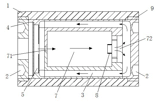
[0006] However, since the inner space structure of the test chamber 7 has more cylindrical edges and corners, these edges and corners will hinder the flow of the air flow, and produce a vortex zone that disturbs the normal flow of the air flow, and the air flow enters the test from the inlet nozzle 71 of the small opening. The sudden change of the rear section of the chamber 7 will also cause multiple eddy current areas to be formed inside the test chamber 7, causing uneven dispersion of the airflow beam hitting the thermal element 8, reducing the measurement accuracy and seriously affecting the accuracy of the measurement results

Method used


Image

  • Minitype airflow type gyro
  • Minitype airflow type gyro
  • Minitype airflow type gyro

Examples


Embodiment Construction

[0026] The present invention will be further described below in conjunction with specific examples.

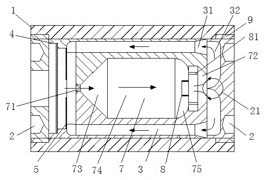
[0027] like figure 1 Shown is that the small air flow gyroscope of the present invention includes a housing 1, a disc spring 4, a piezoelectric pump 5, a test cavity 7, a thermal sensor 8 and a signal processing circuit (not shown in the figure); the housing 1 is composed of a side wall It is composed of end caps 2 covering both ends of the side wall. The side wall is thin-walled and cylindrical. The end cap 2 at one end is provided with an insulator for power supply wires and signal wires leading out of the signal outlet 9 of the housing 1. When the power supply and After the lead is drawn out, the signal lead-out port 9 is closed to make the inside of the housing 1 a closed space.

[0028] The test cavity 7 is arranged at the center position in the housing 1, and the left end of the test cavity 7 in the figure is provided with an air inlet nozzle 71, and the air inlet nozzl...


PUM


Abstract

The invention relates to a minitype airflow type gyro. The gyro comprises a shell, wherein the two ends of the shell are sealed through an end cover, and the shell is internally provided with a testing cavity body; the testing cavity body is formed with an air inlet nozzle and an air outlet; a thermosensitive element is arranged in the position approaching the air outlet in the testing cavity body; a gas circulation channel is arranged between the shell and the testing cavity body and is used for connecting the air inlet nozzle and the air outlet; the outer side of the air inlet nozzle of the testing cavity body is provided with a piezoelectric pump used for pressing the gas into the testing cavity body, and the testing cavity body, the gas circulation channel and the piezoelectric pump form a closed cycle of the gas; the testing cavity body is in central symmetry along the radial direction; from the air inlet nozzle to the air outlet, the testing cavity body successively comprises a guide section used for guiding the diffusion angle of the airflow bundle, a flow section used for leading an airflow bundle to flow smoothly and a confluence section used for collecting the airflow bundle to the air outlet through a smooth inclined plane; and the thermosensitive element is arranged on the tail end of the confluence section. The minitype airflow type gyro provided by the invention has the advantages that the measuring accuracy and the stability of the gyro operation are improved.

Description

[0001] technical field [0002] The invention relates to a device for measuring the angular velocity of a moving body by means of an air jet, in particular to a small air flow gyroscope. [0003] Background technique [0004] The airflow jet gyro device is a solid-state inertial device that has the function of a gyro without the rotating part of the traditional gyro and without the suspension parts of the piezoelectric gyro. The airflow angular velocity sensor uses gas as the sensitive mass, its mass is extremely small, and it is widely used in the field of angular velocity measurement due to its advantages of low cost, short response time, and strong impact resistance. [0005] Airflow gyro in the prior art, such as figure 1 As shown, it includes a housing 1, the two ends of the housing 1 are closed by the end cap 2, and a cylindrical test chamber 7 is arranged in the housing 1, an air inlet nozzle 71 is provided at one end of the test chamber 7, and an air inlet nozzle 7...

Claims


Application Information

Patent Timeline
Patent Type & Authority Applications(China)
IPC IPC(8): G01C19/58
Inventor 朴林华张保丽梅传志陈敬波
Owner BEIJING INFORMATION SCI & TECH UNIV
Learn More