Portable failure detection system and method for aero-engine gas path component

A technology for aero-engines and gas circuit components, which is applied in the field of fault detection systems for portable aero-engine gas circuit components, can solve problems such as abnormal exhaust static signals, changes in the overall static charge level of exhaust gas, and influence on normal tissue combustion, etc., achieving low system cost, Ease of implementation and safety-enhancing effects

Inactive Publication Date: 2013-03-20
NANJING UNIV OF AERONAUTICS & ASTRONAUTICS
View PDF3 Cites 27 Cited by
  • Summary
  • Abstract
  • Description
  • Claims
  • Application Information

AI Technical Summary

Problems solved by technology

[0006] A failure in any part of the combustion system may affect the normal tissue combustion, resulting in excessive soot particles, causing abnormalities in the static signal of the exhaust gas, and failure of other gas circuit components, such as ablation and block loss of hot end components , rubbing of rotating parts, inhalation of foreign objects, etc. will also produce faulty particles, resulting in changes in the overall electrostatic charge level of the exhaust gas, and then causing abnormal electrostatic signals of the exhaust gas, and the change rules of the static signal signals caused by different faults are different, which is based on the exhaust gas Electrostatic signal fault monitoring and diagnosis of gas circuit components provide the possibility
[0007] Electrostatic monitoring technology is a new type of gas path state monitoring technology with very promising application prospects. It is of great significance to detect faults in advance, prevent air parking and ensure flight safety. However, due to technical factors and airworthiness limitations, it is currently not available in civil aviation. Electrostatic sensor installed on the engine

Method used


Image

  • Portable failure detection system and method for aero-engine gas path component
  • Portable failure detection system and method for aero-engine gas path component
  • Portable failure detection system and method for aero-engine gas path component

Examples


Embodiment

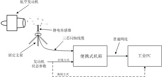
[0045] This method is illustrated with the help of data collected from a certain engine test run. Firstly, the electrostatic signals and fuel flow in each steady state collected by a test run are analyzed. According to the exhaust static signal given by formula (1), the RMS value of the electrostatic signal is fitted with The change trend of fuel flow, such as Figure 4 shown. Under normal circumstances, the RMS value of the static signal should fluctuate within a certain range centered on the baseline. If it deviates too much, it indicates that the static charge level in the gas circuit has a significant change under the same fuel supply condition, which is usually It is caused by the sudden failure of air circuit components or the inhalation of foreign objects. Failures in the combustion chamber, such as carbon deposits in the nozzle and poor combustion organization, are likely to cause a significant increase in soot particles in the exhaust gas, resulting in a long-term de...


PUM


Abstract

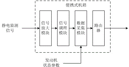
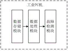
The invention relates to a portable failure detection system and method for an aero-engine gas path component. According to a principle that the tail gas electrostatic-charge level keeps in a certain level range under the condition that an aero-engine is failure-free, and the tail gas electrostatic-charge level can change once the gas path component has a failure, the system and the method detect the health status of the aero-engine gas path component. The system comprises a tail gas static-electricity monitoring sensor subsystem, a signal conditioning, collecting and transmitting subsystem and an industrial PC (Personal Computer). First, a baseline model of engine tail gas electrostatic signals is established, and the health status of an engine is judged through deviation of the analyzed and actually-measured characteristic parameters of the tail gas electrostatic signals and a baseline value. Aiming at the problems of false dismissal and early warning lag in the traditional engine status monitoring method, the invention designs the portable failure detection system for the gas path components. The system is used for engine ground run, can increase the safety of the engine, is low in cost, and is easily realized in engineering.

Description

technical field [0001] The invention belongs to the field of aero-engine state monitoring and fault diagnosis, and more specifically relates to a portable aero-engine air circuit component fault detection system and method. Background technique [0002] The existing state monitoring of air circuit components of aero-engines is mainly based on air circuit performance parameters and vibration signals, etc., which play an important role in ensuring the safety of engine operation. However, traditional methods such as air circuit analysis and rotor vibration monitoring need to The existence of the fault can only be detected, and the fault is often not found in time, and there are potential safety hazards; in addition, the information obtained by these monitoring methods is limited, and it is difficult to comprehensively evaluate the health status of the engine gas circuit components, and sometimes Security accidents also reflect the insufficiency of existing monitoring technologi...

Claims


Application Information

Patent Timeline
Patent Type & Authority Applications(China)
IPC IPC(8): G01M15/00G01M15/10
Inventor 左洪福孙见忠刘鹏鹏
Owner NANJING UNIV OF AERONAUTICS & ASTRONAUTICS
Why Eureka
Try Eureka