Direct earth capacitance gauge in converting station power distribution system

A technology of power distribution system and capacitance to ground, which is applied in the direction of emergency protection circuit devices, measuring devices, and measuring electrical variables for limiting overcurrent/overvoltage, and can solve problems such as increasing system risks and endangering large phase-to-phase short circuits. Achieve the effect of avoiding system risk and ensuring measurement accuracy

Inactive Publication Date: 2013-03-20
广州同汇盛南站产业发展有限公司
View PDF8 Cites 8 Cited by
  • Summary
  • Abstract
  • Description
  • Claims
  • Application Information

AI Technical Summary

Problems solved by technology

The problem with this method is that ground faults are deliberately created to increase system risk. If a ground fault occurs in other p

Method used


Image

  • Direct earth capacitance gauge in converting station power distribution system
  • Direct earth capacitance gauge in converting station power distribution system
  • Direct earth capacitance gauge in converting station power distribution system

Examples


Embodiment Construction

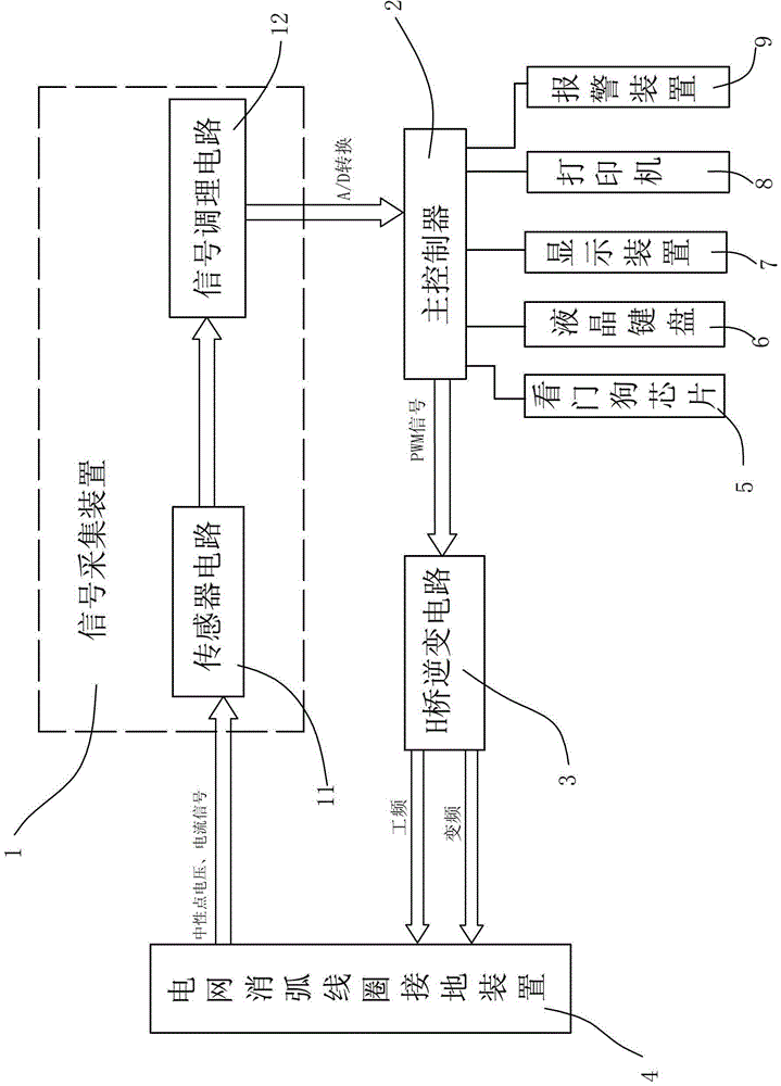
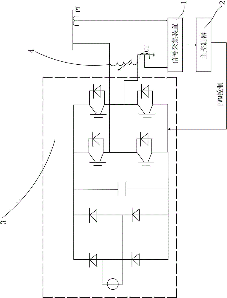
[0013] refer to figure 1 and figure 2 , a ground-to-ground capacitance measuring instrument in a substation power distribution system of the present invention includes a signal acquisition device 1 for collecting current and voltage signals in an arc suppression coil, a main controller 2 with control and analysis functions, and a For the H-bridge inverter circuit 3 that provides commutation signals to the power grid, the signal acquisition device 1, the main controller 2, and the H-bridge inverter circuit 3 are connected in sequence, wherein the input terminal of the signal acquisition device 1, the H-bridge inverter The output terminal of the transformation circuit 3 is connected to the grounding device 4 of the arc suppressing coil of the grid. In view of the current arc suppressing coil having an operation mode close to the resonance point with additional damping resistance and an operation mode far away from the resonance point without damping resistance, the main contro...


PUM


Abstract

The invention discloses a direct earth capacitance gauge in a converting station power distribution system. The direct earth capacitance gauge comprises a signal acquisition device, a master controller, and an H-bridge inverter circuit, wherein the signal acquisition device is used for acquiring current signals and voltage signals in an arc suppression coil, the master controller has control, analysis, and operation functions, and the H-bridge inverter circuit is used for supplying converting signals for an electric network. The signal acquisition device, the master controller, and the H-bridge inverter circuit are successively connected, wherein an input end of the signal acquisition device and an output of the H-bridge inverter circuit are connected with a grounding device of the electric network arc suppression coil. Compared with a traditional single-phase metal grounding method, the method of the direct earth capacitance gauge is free of manufacturing fault intentionally, avoids system risk, and aims at that the arc suppression coil has a running mode added with damping resistance close to resonance point and a running mode without being added with the damping resistance far from the resonance point at present, and then two different measuring ways, namely a two-point method and a variable-frequency method, are respectively designed. Can not only precision of direct earth capacitance of the system be guaranteed, but also the direct earth capacitance gauge cannot bring negative influence to the system.

Description

technical field [0001] The invention relates to a ground capacitance measuring instrument in a power distribution system of a substation. Background technique [0002] When a single-phase ground fault occurs in the power grid, the arc suppression coil grounding can use the inductance current generated by the arc suppression coil to compensate the capacitance current of the ground point, reduce the recovery speed of the fault phase voltage, and automatically extinguish the arc at the ground point. Therefore, it is an important condition to accurately measure the capacitance value of the system to the ground to generate the correct inductive current for the arc suppression coil, thereby compensating the capacitance current of the grounding point, so that the arc at the grounding point is automatically extinguished, and the residual grounding current is smaller. The traditional measurement of capacitive current is mainly single-phase metal grounding method. Under the condition...

Claims


Application Information

Patent Timeline
IPC IPC(8): G01R27/26
CPCH02H9/08
Inventor 吴明玉洪君李建会
Owner 广州同汇盛南站产业发展有限公司
Why Eureka
Try Eureka