Display panel and electrowetting display equipment

An electrowetting display and display panel technology, used in static indicators, optics, instruments, etc., can solve the problems of low brightness, increased production process steps, small color gamut, etc., and achieve high luminous purity, high display quality, and large size. The effect of color gamut

Active Publication Date: 2013-03-20
BOE TECH GRP CO LTD
View PDF8 Cites 11 Cited by
  • Summary
  • Abstract
  • Description
  • Claims
  • Application Information

AI Technical Summary

Problems solved by technology

[0004] In existing electrowetting display devices, non-polar dyeing liquid 6 is prepared by adding oil-soluble dyes or pigments of corresponding colors to non-polar liquids such as oil. The oil-soluble dyes or pigments themselves do not emit light, and The brightness is very dark, which makes the existing electrowetting display devices have a small color gamut, low brightness, and poor display picture quality
[0005] The Chinese patent with the application number 201220063851.7 discloses an "electrowetting display device", which uses the property of quantum dots to emit visible light when excited by external energy, and dissolves oil-soluble quantum dots in non-polar liquids such as toluene In the process, the brightness of the device can be increased to 50-80%, but the ability of oil-soluble quantum dots to dissolve in non-polar solvents is poor, so the advantages of stimulated light emission of quantum dots cannot be fully utilized; at the same time, when realizing the dark state mode , the device needs to set a UV blocking film under the non-polar liquid to absorb UV light, so as to prevent the quantum dots cohesively above it from being excited to produce visible light
The setting of the ultraviolet light blocking film makes the structure of the device complicated, increases the manufacturing process steps, and correspondingly increases the cost

Method used


Image

  • Display panel and electrowetting display equipment
  • Display panel and electrowetting display equipment
  • Display panel and electrowetting display equipment

Examples


Embodiment Construction

[0024] In order to enable those skilled in the art to better understand the technical solutions of the present invention, the display panel and the electrowetting display device of the present invention will be further described in detail below with reference to the drawings and specific embodiments.

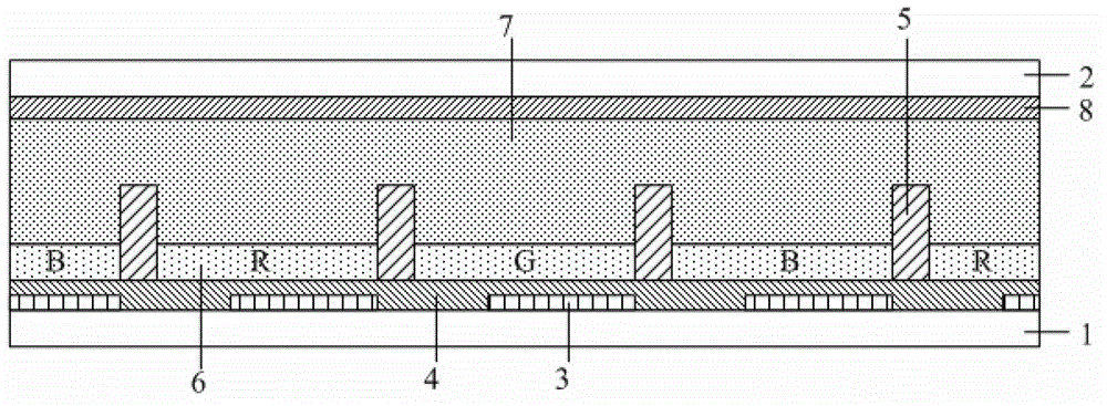
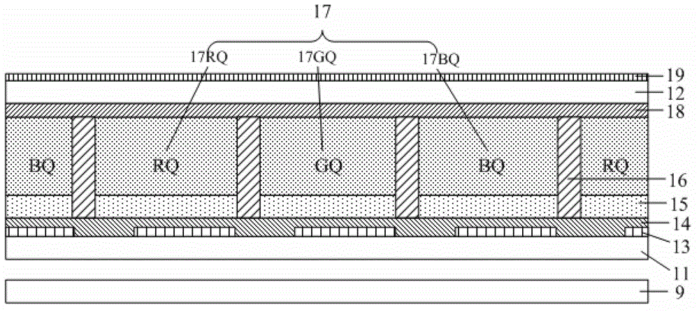
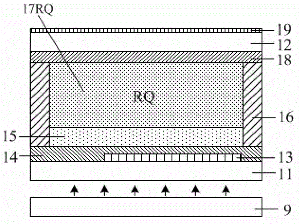
[0025] A display panel, comprising a pixel electrode substrate, a common electrode substrate, a plurality of pixel electrodes, a dielectric layer and a barrier plate, the plurality of pixel electrodes are arranged on the pixel electrode substrate at intervals, and the dielectric layer is arranged on the on the pixel electrode substrate and make the pixel electrode embedded therein, the barrier plate is located between the adjacent pixel electrodes, the display panel also includes a non-polar liquid capable of absorbing ultraviolet light and the polarity of the sub-dots liquid, the non-polar liquid and the polar liquid are sequentially arranged on the dielectric layer in the space...


PUM


Abstract

The invention belongs to the field of display equipment, and particularly relates to a display panel, and electrowetting display equipment. The display panel provided by the invention comprises a pixel electrode substrate, a common electrode substrate, a plurality of pixel electrodes, a dielectric layer and baffle plates, wherein the pixel electrodes are arranged on the pixel electrode substrate at intervals; the dielectric layer is arranged on the pixel electrode substrate, and the pixel electrodes are buried in the dielectric layer; the baffle plates are positioned between adjacent pixel electrodes; the display panel further comprises non-polar liquid capable of absorbing ultraviolet light and polar liquid containing quantum dots; and the non-polar liquid and the polar liquid are arranged in sequence on the dielectric layer in space surrounded by adjacent baffle plates. The invention provides the electrowetting display equipment with the display panel. The electrowetting display equipment has relatively high luminescence purity, relatively high brightness and high display quality.

Description

technical field [0001] The invention belongs to the field of display devices, and in particular relates to a display panel and an electrowetting display device. Background technique [0002] The phenomenon of electrowetting (Electrowetting) is to use the inherent natural force of the interface between oil and water, using a highly hydrophobic material that can remove water from the surface and use the oil film as the medium to form a method of separating the oil phase and the water phase . Among them, the wetting effect of the water-resistant surface can change the interface properties by changing the voltage, making the original water-resistant surface more hydrophilic (or wet), hence the name electrowetting. Electrowetting Display (Electrowetting Display) is the use of electrowetting phenomenon or electrocapillary (Electrocapillary) phenomenon, when the liquid is subjected to an electric field to change the surface free energy (Free Surface Energy) of the liquid, so that ...

Claims


Application Information

Patent Timeline
Patent Type & Authority Applications(China)
IPC IPC(8): G02B26/02G09G3/34
Inventor 张锋姚琪谷敬霞
Owner BOE TECH GRP CO LTD
Why Eureka
Try Eureka