Magnetic coupling reduction box

A technology of reducer and magnetic force, applied in the field of magnetic transmission device, can solve the problems of complex structure, untargeted mechanical transmission device, high energy consumption, etc.

Inactive Publication Date: 2013-03-20
CCTEG SHENYANG RES INST
View PDF5 Cites 0 Cited by
  • Summary
  • Abstract
  • Description
  • Claims
  • Application Information

AI Technical Summary

Problems solved by technology

In this case, most of the mechanical transmission devices used are not targeted for coal mine production, have poor safety and have a series of problems such as high energy consumption and low life, which have brought hidden dangers to the safe production of coal mines.
[0004] First, due to the complex structure of the mechanical transmission when realizing stepless speed regulation, the complex structure increases the workload and cost of maintenance, while the stepped speed regulation has the problem of high energy consumption
[0005] Second, during mechanical transmission, the rotation is achieved by the meshing of the gears. Long-term meshing will reduce the life of the gears and affect the normal operation of the mechanical equipment.
[0006] Third, the traditional mechanical transmission has vibrations when starting and stopping, and affects the service life of other components
[0007] Fourth, the traditional mechanical transmission is difficult to achieve overload protection, and there are great safety hazards

Method used


Image

  • Magnetic coupling reduction box
  • Magnetic coupling reduction box

Examples


Embodiment

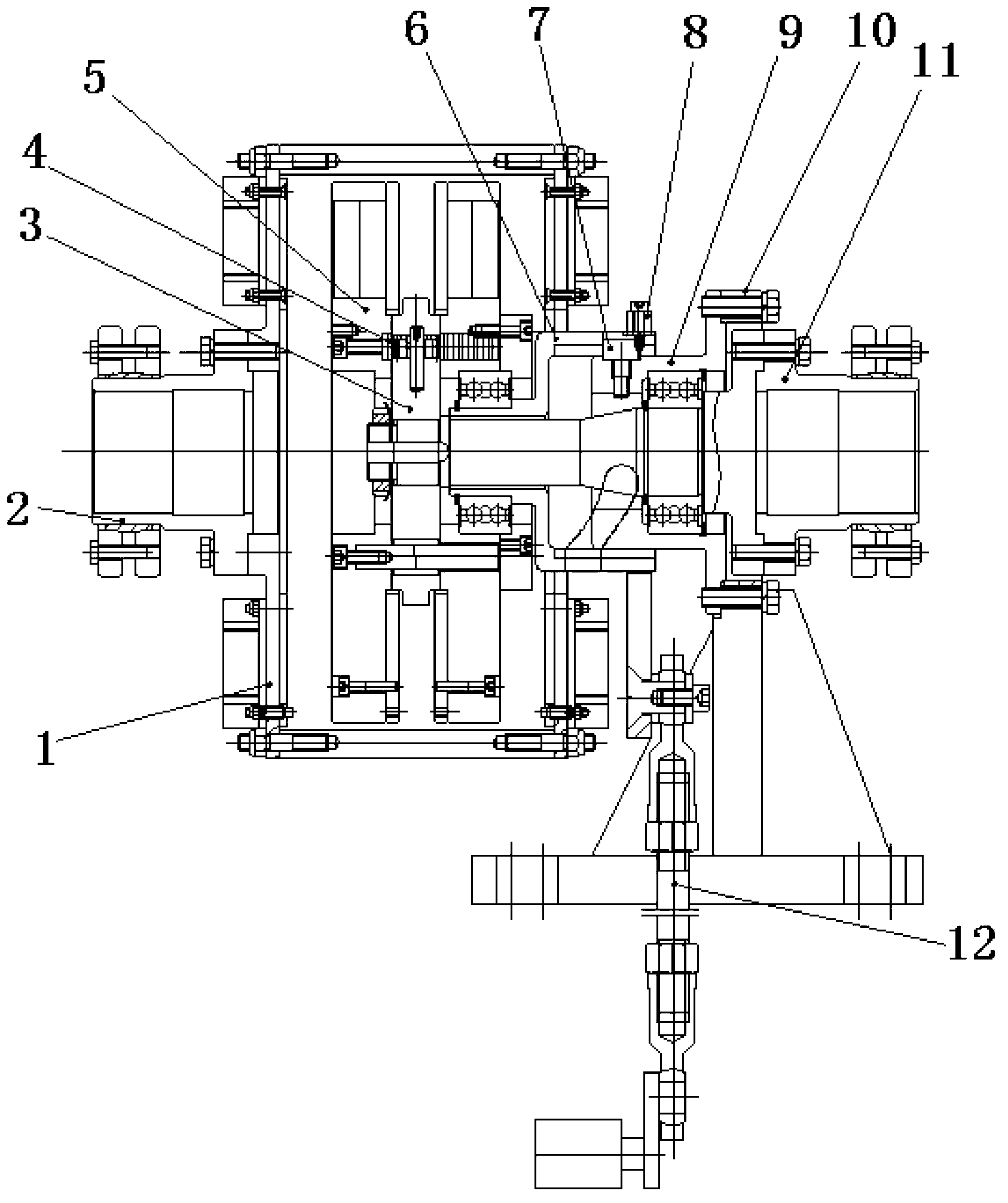
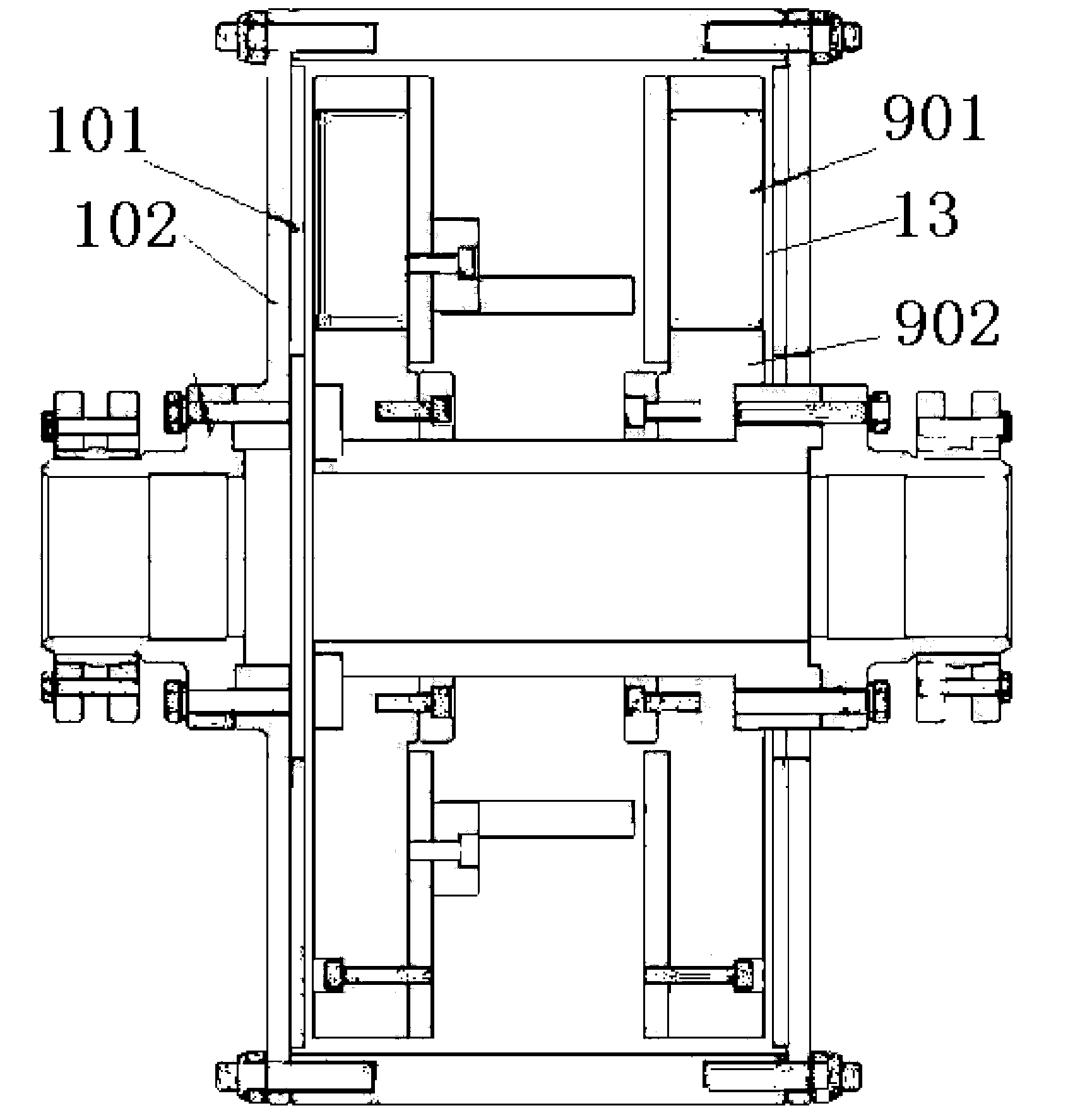
[0023] This embodiment provides a magnetic coupling reducer, which is characterized in that: the magnetic coupling reducer includes an input assembly 1, a left coupling 2, a connecting body 3, a rack 4, a magnet assembly 5, and a speed regulating jacket 6 , roller 7, handle 8, output shaft assembly 9, support 10, right coupling 11, control mechanism 12;

[0024] Among them: the input assembly 1 and the output shaft assembly 9 are connected through the magnet assembly 5, the left coupling 2 is connected with the input assembly 1, the connecting body 3 is connected with the rack 4, and the speed regulating jacket 6 is connected with the output shaft assembly through the roller 7 9 connection, the output shaft assembly 9 is connected with the right coupling 11, the operating mechanism 12 is connected with the output shaft assembly 9, the handle 8 is installed on the speed regulating sleeve 6, and the distance between the input assembly 1 and the output shaft assembly 9 can be adju...


PUM


Abstract

Provided is a magnetic coupling reduction box. The magnetic coupling reduction box comprises an input assembly, a left coupling, a connector, a rack, a magnet assembly, a speed regulation jacket, a roller, a handlebar, an output shaft assembly, a supporting seat, a right coupling and a control mechanism. The input assembly is connected with the output shaft assembly through the magnet assembly, the left coupling is connected with the input assembly, the connector is connected with the rack, the speed regulation jacket is connected with the output shaft assembly through the roller, the output shaft assembly is connected with the right coupling, the control mechanism is connected with the output shaft assembly, and the handlebar is installed on the speed regulation jacket. The magnetic coupling reduction box has the advantages of solving the problems that speed change classification in existing mechanical transmission is high in energy consumption and cost and difficult to maintain, does not have overload protection, or hidden safety risks and shakes exist on the overload protection, the overload protection influences service life of other components and the like, solving the problems to the maximum, and achieving safe operation.

Description

technical field [0001] The invention relates to the field of magnetic transmission devices, in particular to a magnetic coupling speed reducer. Background technique [0002] In the coal mining industry, production safety has become the most important issue restricting coal production. The safety guarantee mechanism of coal mining enterprises is a multi-factor, multi-link, dynamic and complex operating system. To reverse the passive situation of safety production in coal enterprises, we must pay attention to the development of safety technology and equipment, and eliminate unsafe factors from the details. [0003] At present, most of the transmission devices used in coal mines are traditional and backward mechanical transmissions. This kind of transmission device is not targeted in the application of coal mine production. Many details cannot meet the safety standards of coal mines, and there are energy consumption and easy Disadvantages such as wear and tear. As coal mine ...

Claims


Application Information

Patent Timeline
Patent Type & Authority Applications(China)
IPC IPC(8): H02K51/00H02K49/04
Inventor 祝钊白雪冯智鹏王国辉刘扬
Owner CCTEG SHENYANG RES INST
Why Eureka
Try Eureka