Magnetic coupling gearbox

A variable speed, magnetic technology, applied in the direction of electromechanical device, control mechanical energy, electromechanical transmission device, etc., can solve the problem of mechanical transmission device not being targeted, affecting the service life of other parts, poor safety, etc.

Inactive Publication Date: 2013-03-20
CCTEG SHENYANG RES INST
View PDF4 Cites 2 Cited by
  • Summary
  • Abstract
  • Description
  • Claims
  • Application Information

AI Technical Summary

Problems solved by technology

In this case, most of the mechanical transmission devices used are not targeted for coal mine production, have poor safety and have a series of problems such as high energy consumption and low life, which have brought hidden dangers to the safe production of coal mines.
[0004] First, due to the complex structure of the mechanical transmission when realizing stepless speed regulation, the complex structure increases the workload and cost of maintenance, while the stepped speed regulation has the problem of high energy consumption
[0005] Second, during mechanical transmission, the rotation is achieved by the meshing of the gears. Long-term meshing will reduce the life of the gears and affect the normal operation of the mechanical equipment.
[0006] Third, the traditional mechanical transmission has vibrations when starting and stopping, and affects the service life of other components
[0007] Fourth, the traditional mechanical transmission is difficult to achieve overload protection, and there are great safety hazards

Method used


Image

  • Magnetic coupling gearbox
  • Magnetic coupling gearbox
  • Magnetic coupling gearbox

Examples


Embodiment

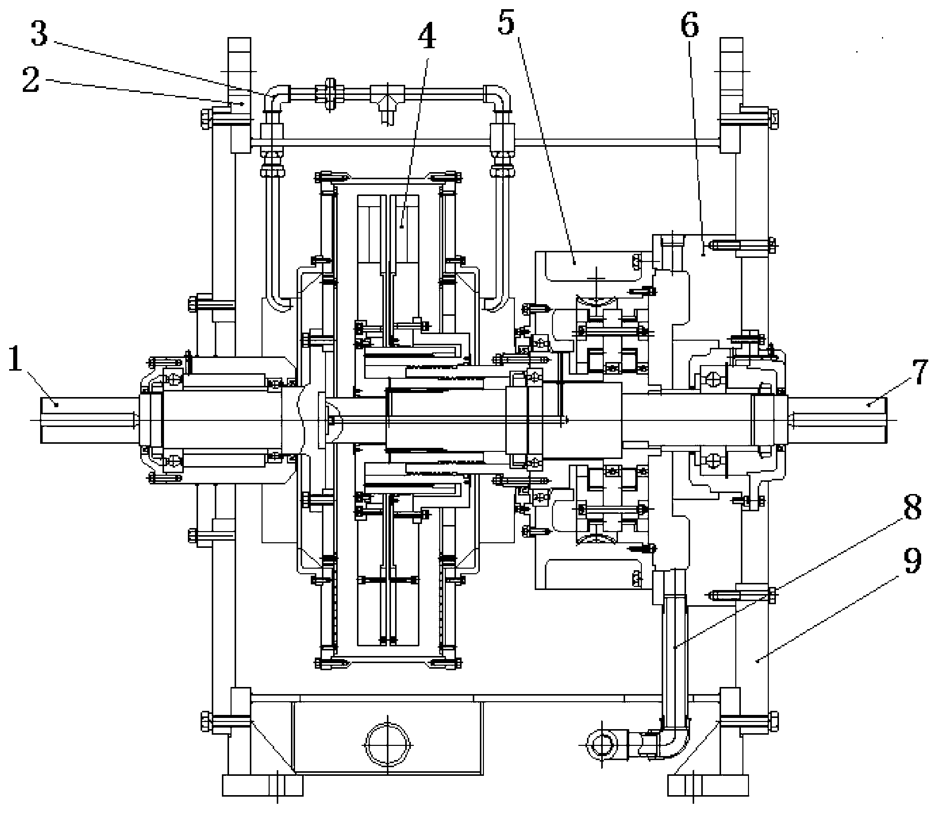
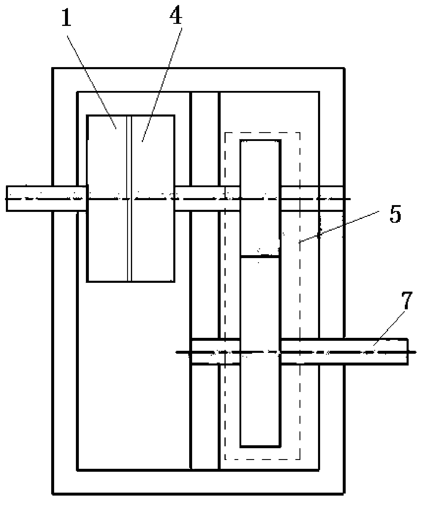
[0026] This embodiment provides a magnetic coupling speed changer, which is characterized in that: the magnetic coupling speed changer includes an input assembly speed regulating gear system 1 speed regulating gear system, a box body speed regulating gear system 2 speed regulating gear systems, an oil and water circuit System Flying Gear System 3 Flying Gear System, Output Assembly Flying Gear System 4 Flying Gear System, Flying Gear System Flying Gear System 5 Flying Gear System, Flying Gear System Base Flying Gear System 6 Flying Gear System, output shaft speed regulating gear system 7 speed regulating gear systems, oil return pipe speed regulating gear system 8 speed regulating gear systems, output flange speed regulating gear system 9 speed regulating gear systems;

[0027] The input assembly speed control gear system 1 speed control gear system and the output assembly speed control gear system 4 speed control gear system are magnetically coupled, and there is an adjustable...


PUM


Abstract

Provided is a magnetic coupling gearbox. The magnetic coupling gearbox comprises an input assembly, a box body, an oil-water line system, an output assembly, a speed control gear system, a speed control gear system base seat, an output shaft, an oil return pipe and an output end flange. The input assembly is coupled with the output assembly through magnetic force, adjustable air gaps are arranged between the input assembly and the output assembly, and the speed control gear system is connected with the output assembly and installed on the speed control gear system base seat. The output shaft is connected with the speed control gear system, the output end flange is arranged on the box body, and the oil-water line system is connected with the oil return pipe. The input assembly is steel rotors with copper rings, and the output assembly is permanent-magnetic stators and is aluminum stators with permanent-magnetic materials. The magnetic coupling gearbox has the advantages of solving the problems that speed change classification in existing mechanical transmission is high in energy consumption and cost and difficult to maintain, does not have overload protection, or hidden safety risks and shakes exist on the overload protection, the overload protection influences service life of other components and the like, solving the problems to the maximum, and achieving safe operation.

Description

technical field [0001] The invention relates to the field of magnetic transmission devices, in particular to a magnetic coupling speed changer. Background technique [0002] In the coal mining industry, production safety has become the most important issue restricting coal production. The safety guarantee mechanism of coal mining enterprises is a multi-factor, multi-link, dynamic and complex operating system. To reverse the passive situation of safety production in coal enterprises, we must pay attention to the development of safety technology and equipment, and eliminate unsafe factors from the details. [0003] At present, most of the transmission devices used in coal mines are traditional and backward mechanical transmissions. This kind of transmission device is not targeted in the application of coal mine production. Many details cannot meet the safety standards of coal mines, and there are energy consumption and easy Disadvantages such as wear and tear. As coal mine ...

Claims


Application Information

Patent Timeline
Patent Type & Authority Applications(China)
IPC IPC(8): H02K7/116H02K51/00
Inventor 祝钊赵克涛王启明白雪刘小菊
Owner CCTEG SHENYANG RES INST
Why Eureka
Try Eureka