
Multi-point excitation source loudspeaker sound box

A multi-point excitation source and speaker technology, applied in the direction of sensors, transducer shells/cabinets/brackets, electrical components, etc., can solve the problems of difficult manufacturing and high cost, achieve good performance and price, reduce thickness, and ingenious and reasonable structure Effect

Inactive Publication Date: 2013-03-20
WUXI JIEFU ELECTROACOUSTIC
View PDF6 Cites 4 Cited by
  • Summary
  • Abstract
  • Description
  • Claims
  • Application Information

AI Technical Summary

Problems solved by technology

In order to improve the driving force of the magnetic circuit system, a thicker and larger magnetic circuit structure must be used, which makes it difficult to achieve a product thickness of less than 8mm, but the speaker products using this structure have better sound quality and are easier to manufacture
There is a flat-panel speaker sound radiation technology in foreign countries. The principle is that through a flat thin plate and a specific excitation source, the thin plate acts as a high-order vibration mode of random vibration radiation sound, and its sound radiation is the joint action of many bending vibration modes. The result is that it is thin, and it is relatively easy to make the product thickness within 8mm, and the area can be large or small, and the directivity is wide, but it is difficult to manufacture and the cost is high. It is not suitable for LED TV speakers with good sound quality and low cost. requirements

Method used


Image

  • Multi-point excitation source loudspeaker sound box
  • Multi-point excitation source loudspeaker sound box
  • Multi-point excitation source loudspeaker sound box

Examples


Embodiment Construction

[0017] The present invention will be further described below in conjunction with specific drawings and embodiments.

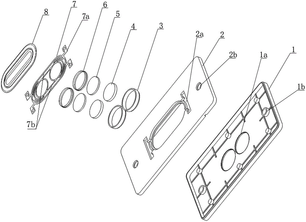
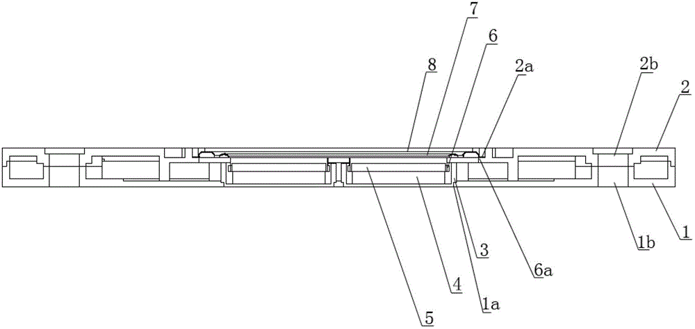
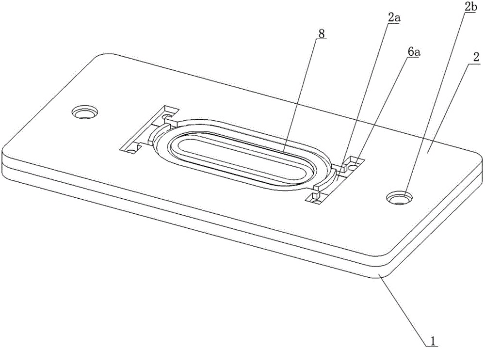
[0018] As shown in the figure: the multi-point excitation source speaker box in the embodiment is mainly composed of lower shell 1, upper shell 2, U iron 3, magnet 4, magnetic pole core 5, voice coil 6, positioning support piece 7 and sound cone 8 and other components Composition, the lower shell 1, the upper shell 2, the positioning support piece 7 and the sound cone 8 all have only one; the U iron 3, the magnet 4, the magnetic pole core 5 and the voice coil 6 each have two, and they form two sets of magnetic circuit systems .

[0019] Such as Figure 1~Figure 4 As shown, the bottom of the lower case 1 is provided with two middle holes 1a distributed along the long axis direction, each middle hole 1a is provided with a magnetic circuit system, and the lower case 1 is provided with a lower case installation hole 1b, The upper shell 2 is provided with an upper...


PUM


Abstract

The invention relates to a multi-point excitation source loudspeaker sound box. At least two middle holes distributed along the direction of a long axis are arranged at the bottom of a lower casing, a magnetic circuit system is disposed in each middle hole, an upper casing is tightly combined with the lower casing, a positioning groove is arranged on the upper casing, a single positioning support chip and a single sound cone are arranged, the positioning support chip is installed in the positioning groove, the positioning support chip is divided into two half pieces which are symmetrical along the direction of the long axis, a plurality of half positioning rings are arranged on each half piece of the positioning support chip, the quantity of the half positioning rings is equal to that of the magnetic circuit systems, the plurality of half positioning rings on the two half pieces of the positioning support chip correspondingly form a plurality of complete positioning rings, the lower surface of each complete positioning ring is combined with the tops of voice coils in corresponding magnetic circuit systems, the two half pieces of the positioning support chip extend to form terminals, the terminals are connected with positive and negative poles of leading wires of the voice coils respectively, the sound cone is installed above the positioning support chip, and the lower surface of the sound cone is tightly combined with the upper surface of the positioning groove on the upper casing and the upper surfaces of the complete positioning rings. The multi-point excitation source loudspeaker sound box is ingenious and reasonable in structure and capable of excellently matching with a light emitting diode (LED) television.

Description

Technical field [0001] The present invention belongs to the field of electro -acoustic technology and involves a speaker speaker. Specifically, it is a multi -point incentive source speaker that uses more than two magnetic circuit systems to drive a sound basin (or vibration film). Background technique [0002] In the existing technology, the product thickness requirement of the speaker speaker applied to LED TV is within 8mm.The principle of traditional single -point incentive source dynamic circular speakers is that a power ring is stressed in the magnetic field, which drives a sound basin (or diaphragm) movement, that is, the entire sound basin (or vibration film) is driven by a magnetic circuit system.In order to improve the driving force of the magnetic circuit system, a thicker and larger magnetic circuit structure must be used, which makes it difficult to achieve the thickness of the product within 8mm.There is a kind of flat speaker sound radiation technology abroad. The ...

Claims


Application Information

Patent Timeline
IPC IPC(8): H04R1/02H04R9/06
Inventor 蒋加星蒋正祥叶卫华
Owner WUXI JIEFU ELECTROACOUSTIC
Learn More