Brake cylinder device and disc brake device

A brake cylinder and parking brake technology, which is applied to the types of brakes, brake actuators, axial brakes, etc., can solve the problem of large-scale brake cylinder devices, large-scale disc brake devices, and changes in the diameter of the cylinder body. Large and other problems, to achieve the effect of restraining large-scale

Inactive Publication Date: 2013-03-20
NABLESCO CORP
View PDF9 Cites 13 Cited by
  • Summary
  • Abstract
  • Description
  • Claims
  • Application Information

AI Technical Summary

Problems solved by technology

However, when a large braking force is required, there is a problem that the diameter of the cylinder main body becomes larger, resulting in an increase in the size of the entire brake cylinder device.
In addition, if the brake cylinder device is enlarged, there will also be a problem that the disk brake device will also be enlarged.

Method used


Image

  • Brake cylinder device and disc brake device
  • Brake cylinder device and disc brake device
  • Brake cylinder device and disc brake device

Examples


Embodiment Construction

[0055] Hereinafter, embodiments of the present invention will be described with reference to the drawings. In addition, the brake cylinder device and the disc brake device including the brake cylinder device according to the present invention will be described by taking the case of being used in a railway vehicle as an example. In addition, the drawings are produced with an accuracy equivalent to design drawings.

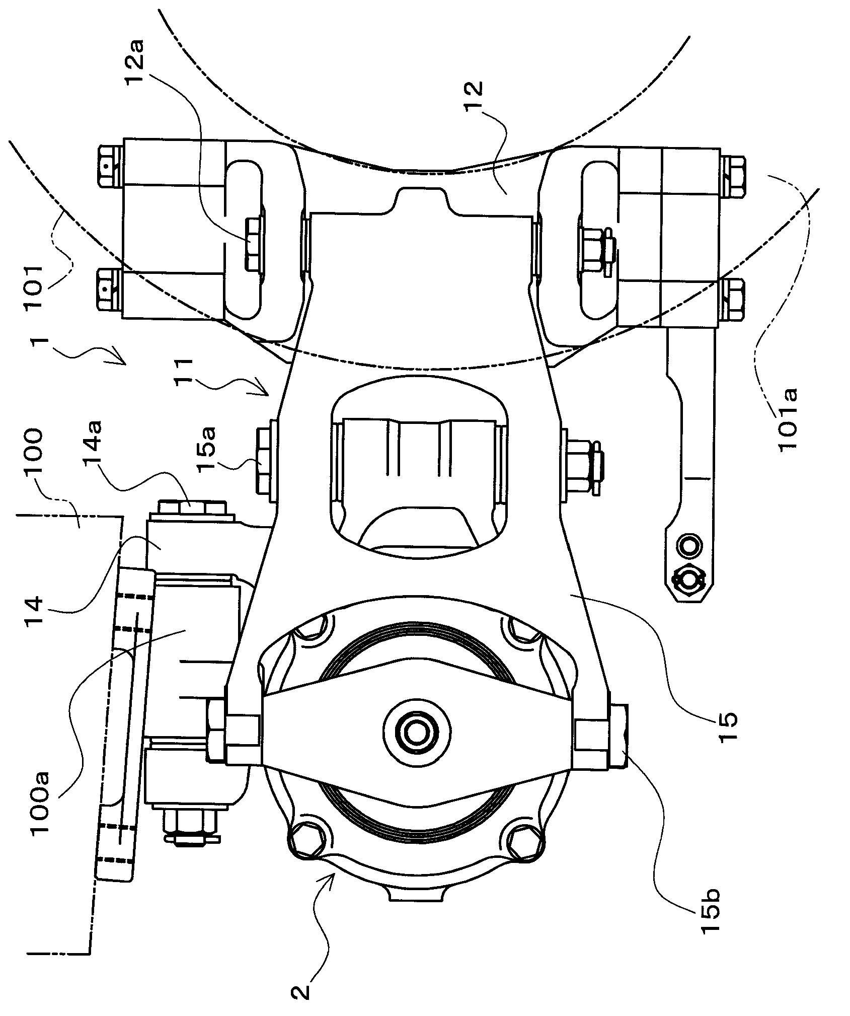
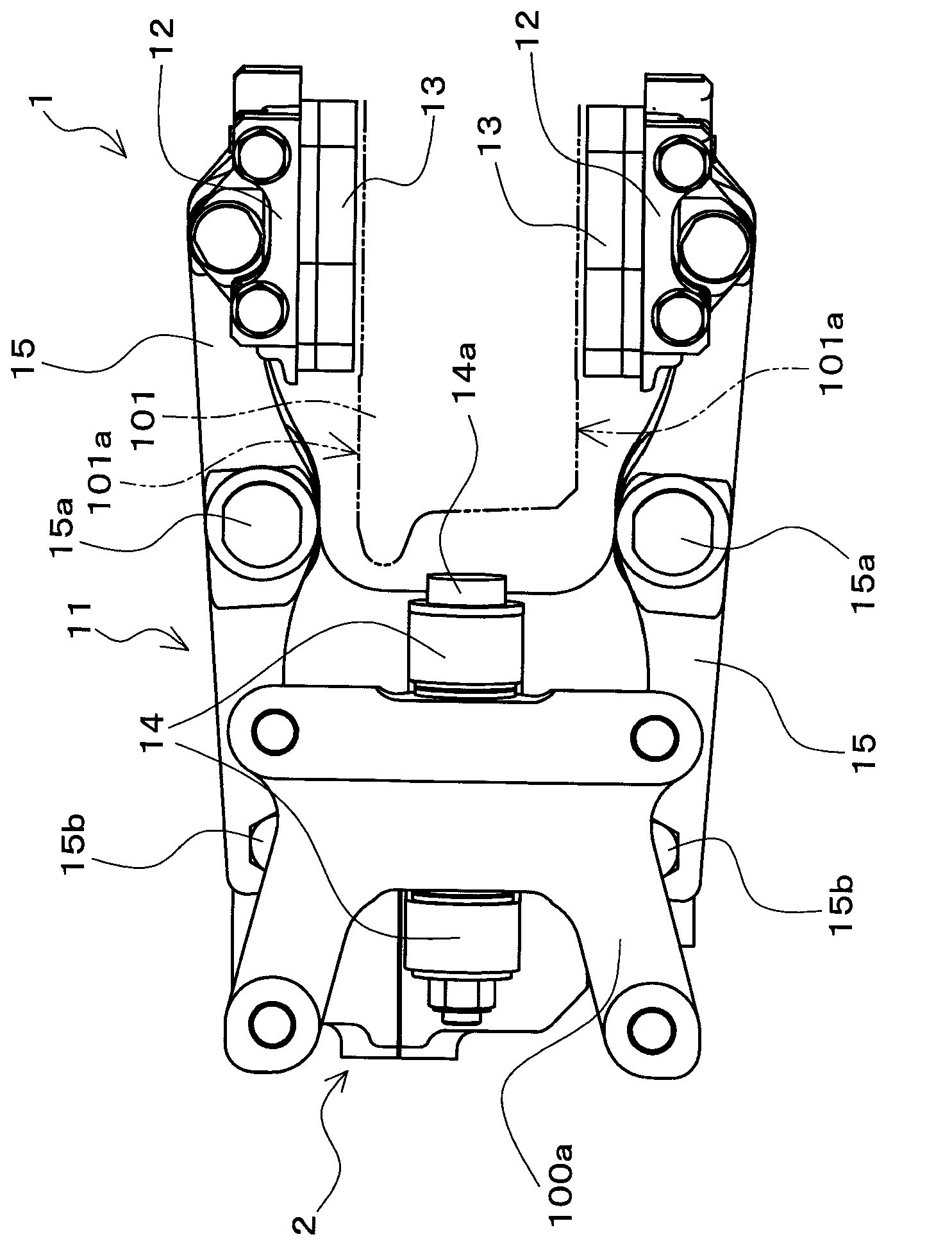
[0056] figure 1 It is a side view of the disc brake device 1 according to the embodiment of the present invention viewed from the axle direction. in addition, figure 2 is viewed from above figure 1 A plan view of the disc brake device 1 shown. figure 1 and figure 2 The shown disc brake device 1 is configured to include the following members, etc.: a brake cylinder device 2; a caliper main body 11 equipped with the brake cylinder device 2 and mounted to a vehicle body 100 in a displaceable manner in the axle direction; A pair of lining plates (12, 12) serving...


PUM


Abstract

Disclosed is a compact brake cylinder device which, while avoiding increases in the size of the device, is capable of increasing the braking force outputted from a brake output unit which moves together with a rod. A rod (22) is provided inside of a cylinder body (20) so as to freely move in the advancing and retracting directions of the cylinder shaft direction. A piston (24) partitions a pressure chamber (44) inside of the cylinder body (20), surrounding the circumference of the rod (22), and moves in a linear direction parallel to the movement direction of the rod (22). By supplying a pressure fluid to the pressure chamber (44), the piston (24) resists the biasing force of a biasing spring (23) and moves in the retracting direction relative to the cylinder body (20). At that time, a force-multiplication mechanism (25) converts the linear direction drive force generated by the piston (24) to a rotational direction, moves the rod (22) in the advancing direction, and multiplies the drive force from the piston (24) to act on the rod (22). A brake output unit (21) moves together with the rod (22) in the advancing direction and outputs a braking force.

Description

technical field [0001] The present invention relates to a brake cylinder device which operates with pressure fluid to move a rod, and a disc brake device having the brake cylinder device. Background technique [0002] Conventionally, as a disc brake device for a rail vehicle having a brake cylinder device, a disc brake device for a rail vehicle having a brake cylinder device disclosed in Patent Document 1 is known. The disc brake device disclosed in Patent Document 1 is configured to protrude a rod in a brake cylinder device using air pressure. In addition, in this disc brake device, a pair of brake rods of the caliper body mounted so as to be displaceable relative to the vehicle in the axle direction are respectively connected at one end side to the rod side of the brake cylinder device and to the circle constituting the cylinder body. The cylindrical members are connected side by side. And, by operating the brake cylinder device as described above, the pair of brake leve...

Claims


Application Information

Patent Timeline
Patent Type & Authority Applications(China)
IPC IPC(8): F16D55/224F16D65/14F16D65/18F16D65/74
CPCF16D2127/04F16D55/2245F16D2125/36F16D2123/00F16D2121/04F16D2121/06F16D65/28F16D65/56
Inventor 大野智也中村丈一
Owner NABLESCO CORP
Why Eureka
Try Eureka