Photogravure press

A gravure printing machine and coating technology, applied in the direction of gravure rotary printing machine, printing machine, rotary printing machine, etc., can solve the problems of reducing productivity, unable to fit tightly, unable to complete transfer printing, etc., to improve labor productivity, improve service life, Good scraping effect

Inactive Publication Date: 2013-03-27
LIAONING CHAOSHUO TOMA TECH STEEL PLATE PRINTING
View PDF8 Cites 18 Cited by
  • Summary
  • Abstract
  • Description
  • Claims
  • Application Information

AI Technical Summary

Problems solved by technology

[0004] Yet the defective that this kind conventional gravure printing machine exists is:
[0005] First, when printing, the ink not only enters the fine depressions of the printing plate cylinder, but also forms on the cylinder around the depressions. In this way, in order to remove the ink located around the depressions on the cylinder, it is necessary to manually remove the above depressions before transferring. removed before entering the ...

Method used


Image

  • Photogravure press
  • Photogravure press

Examples


Embodiment 1

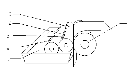
[0031] Such as figure 1 As shown, the present embodiment provides a kind of gravure printing machine, comprises feeding equipment 1, is used for providing coating; Suction roller 2, its peripheral surface is connected with described feeding equipment 1, and described peripheral surface has Form a plurality of depressions in the image area when the paint is filled; the rubber coating roller 3, whose peripheral surface is connected with the suction roller 2, is used to accept the image area formed by the paint on the coating roller 3, and The image area is transferred to the steel plate; it also includes a first scraper 4, which is installed on the first scraper bracket and contacts with the suction roller 2 at a specific angle, and is used to scrape off all of the suction roller 2. The paint outside the image area; the second scraper 5, installed on the second scraper bracket, contacts with the coating roller 2 at a specific angle, and is used to remove the residual paint on th...

Embodiment 2

[0040] Such as figure 2 As shown, the gravure printing machine provided in this embodiment is an improvement on the basis of the embodiment. The main improvement is that a cleaning device 6 is added to clean the second doctor blade 5 and the rubber coating roller 3. paint for cleaning.

[0041] The cleaning device 6 includes a liquid supply tank 61, a cleaning solution delivery pump 62 for pumping the cleaning solution delivery tank 61, a cleaning solution delivery pipeline 63 communicated with the cleaning solution delivery pump 62, and a cleaning solution delivery pipe 63 connected to the cleaning solution delivery pump 62. The spray pipe 64 that conveys pipeline communication, described spray pipe 64 is arranged on the axial top of described rubber coating roller 3, has several spray holes 65 on the described spray pipe 64; Described cleaning device 6 also It includes a cleaning solution recovery tank 66 arranged below the coating roller 3; the cleaning solution recovery ...


PUM

PropertyMeasurementUnit
Thicknessaaaaaaaaaa

Abstract

The invention provides a photogravure press, a coating roller of which is made of rubber to ensure that the coating roller is respectively in flexible contact with an absorbing roller and a to-be-printed steel plate, and thus the tightness of the contact is ensured, a pattern region on the absorbing roller can be completely transferred on the coating roller, and a pattern region on the coating roller also can be completely transferred to the to-be-printed steel plate, therefore a complete pattern region is formed. In addition, the photogravure press provided by the invention comprises a first scraper and a second scraper, wherein the first scraper is used for scraping a coating on the absorbing roller, except for a pit for forming an image region, the second scraper is used for removing residual coating on a rubber roller after transferring, therefore, the defects of lower labor efficiency and poor control precision caused by manual removal of the coating are avoided, and thus the labor productivity is increased and the product quality is ensured. In addition, the first scraper and the second scraper are respectively in contact with the absorbing roller and the coating roller by a specific angle, and thus a better scraping effect can be ensured.

Description

technical field [0001] The invention relates to a gravure printing machine, in particular to a gravure printing machine used for the production of color steel plates, belonging to the field of color steel plate forming. Background technique [0002] The traditional method of forming a color layer on a steel plate is generally to use spraying or heat transfer printing for painting. However, the color layer painted by spraying or heat transfer printing often has poor formability in the later stage, and it is very difficult in the bending process. It is easy to cause the color layer to fall off from the steel plate, and the production efficiency is extremely low. Later, after a lot of research, people used the gravure printing technology traditionally used for paper to produce color steel plates. [0003] A conventional gravure printing machine mainly includes a printing plate cylinder, an ink supply cylinder and an impression cylinder. It is opposite to and in contact with t...

Claims


Application Information

Patent Timeline
IPC IPC(8): B41F9/00B41F9/06B41F35/02
Inventor 唐月平周建平
Owner LIAONING CHAOSHUO TOMA TECH STEEL PLATE PRINTING
Why Eureka
Try Eureka