
light packing box

A packaging box and outer box technology, applied in the field of lamp packaging boxes of short arc discharge lamps, can solve problems such as damage, increased bending moment, cracks in luminous tubes, etc., and achieve the effect of restraining deformation

Inactive Publication Date: 2016-03-09
USHIO DENKI KK
View PDF7 Cites 0 Cited by
  • Summary
  • Abstract
  • Description
  • Claims
  • Application Information

AI Technical Summary

Problems solved by technology

[0009] When the above-mentioned large-sized lamp is transported in the conventional packaging box, since the base portion of the lamp is supported by the lamp holder in the packaging box, the bending moment becomes large due to vibration, impact, etc. during transportation. , resulting in cracks or even damage to the luminous tube

Method used


Image

  • light packing box
  • light packing box
  • light packing box

Examples


Embodiment Construction

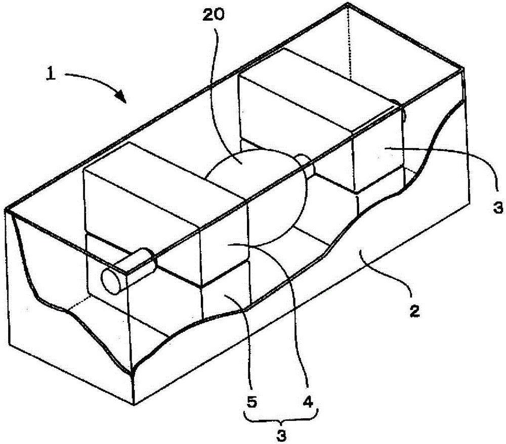
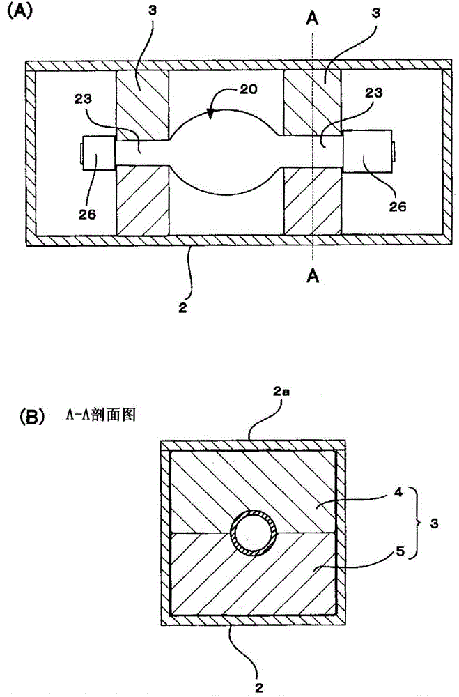
[0050] Such as figure 1 As shown, the lamp packaging box 1 of the present invention is composed of an outer box body 2 and a lamp support member 3 arranged inside it.

[0051] The lamp holder 3 is composed of an upper molded body 4 and a lower molded body 5 having a double-divided structure, and the upper and lower molded bodies are made of cushioning materials such as foamed plastic materials such as polyethylene and polyurethane.

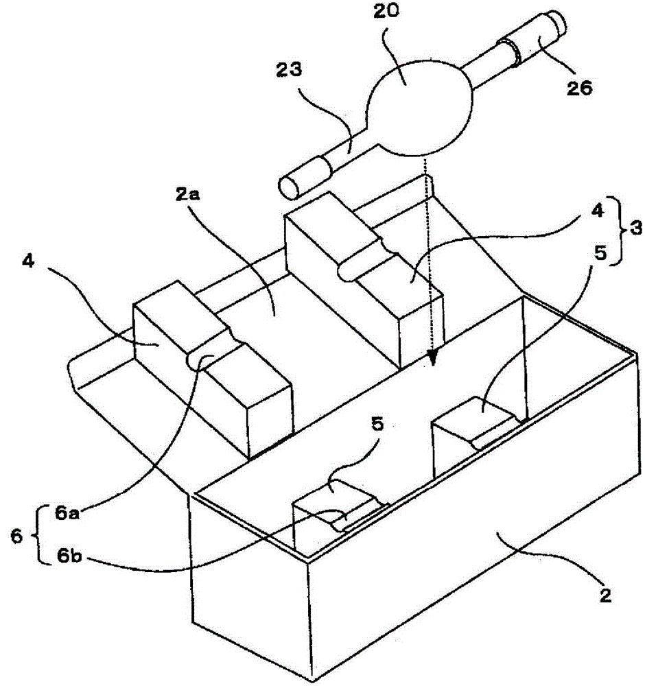
[0052] and if figure 2 As shown, semicircular through-holes 6 a and 6 b are respectively formed in the upper molded body 4 and the lower molded body 5 , and the through-hole 6 is formed through both.

[0053] In this embodiment, as shown in the figure, the upper molded body 4 of the lamp holder 3 is fixed to the back of the switch cover 2a of the outer case 2 by adhesive or the like. Place the lamp 20 on the semicircle through hole 6b of the lower molded body 6, and when the above-mentioned cover 2a is closed afterwards, the upper molded body ...


PUM


Abstract

The box (1) has a pair of lamp support elements (3) in an interior of an outer packaging box body (2) for packing a discharge lamp (20). A lighting tube has a luminescent portion and a pair of electrodes is provided at inside of the luminescent portion, and comprises sealing portions at two ends of the luminescent portion. The lamp support elements maintain exposed portions of the sealing portions of the lighting tube, where the exposed portions are closer than a base side of the luminescent portion.

Description

technical field [0001] The present invention relates to a lamp packaging box, in particular to a lamp packaging box for a short-arc discharge lamp provided with a cap on a sealing portion. Background technique [0002] The shape of a short-arc discharge lamp such as an ultra-high pressure mercury lamp in which mercury is sealed as a luminescent substance, a xenon lamp in which xenon gas is sealed in a high pressure, etc. generally has a shape of a light emitting tube in which branch-shaped sealing parts are continuously formed at both ends of a substantially spherical light emitting part. Inside the luminous tube, the cathode and the anode are arranged opposite to each other. The light-emitting tube is preferably made of quartz glass from the viewpoints of light transmission and heat resistance, and a pair of metal electrodes are arranged in a suspended state inside the sealed glass tube. [0003] The general construct is as Figure 17 shown. [0004] The short-arc dischar...

Claims


Application Information

Patent Timeline
Patent Type & Authority Patents(China)
IPC IPC(8): B65D85/42B65D81/05
CPCB65D5/509B65D85/42
Inventor 细谷茂治河尻晃明福田忠司
Owner USHIO DENKI KK
Learn More