Transducer module

A technology of energy conversion and blocks, which is applied in the direction of transducer diaphragm, loudspeaker transducer fixation, piezoelectric/electrostrictive transducer, etc., which can solve the problems of inconvenience and lack of suitable structure for general products

Inactive Publication Date: 2013-03-27
CHIEF LAND ELECTRONICS CO LTD
View PDF7 Cites 20 Cited by
  • Summary
  • Abstract
  • Description
  • Claims
  • Application Information

AI Technical Summary

Problems solved by technology

[0005] This shows that above-mentioned existing actuator obviously still has inconvenience and defect in structure and use, and urgently needs to be further improved
In order to solve the above-mentioned problems, the relevant manufacturers hav

Method used


Image

  • Transducer module
  • Transducer module
  • Transducer module

Examples


Embodiment Construction

[0043] In order to further explain the technical means and effects of the present invention to achieve the intended purpose of the invention, the specific implementation, structure, characteristics and effects of the energy conversion module proposed according to the present invention will be described below in conjunction with the accompanying drawings and preferred embodiments. Details are as follows.

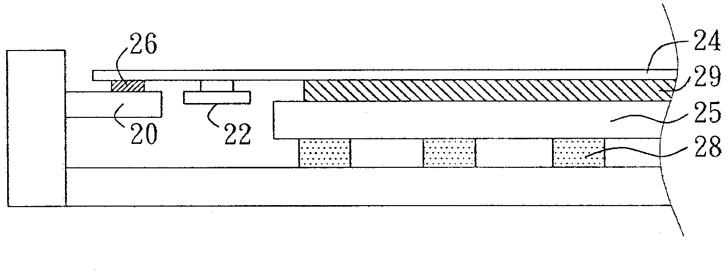
[0044] figure 2 A schematic cross-sectional view of an energy conversion module according to an embodiment of the present invention is shown. The energy conversion module mainly includes a frame body 20 , an actuator 22 , a vibrating plate 24 and an elastic damper 26 . Wherein, the actuator 22 is directly or indirectly coupled to the vibrating plate 24 (such as a touch panel, a substrate, or an operation panel of other man-machine interface), and the vibrating plate 24 is elastically held on the frame body 20 by the elastic damper 26 ( such as pallets or frames). In this ...


PUM


Abstract

The present invention is directed to a transducer module, which includes an actuator that is directly or indirectly coupled to a vibration plate. The transducer module includes a plastic damper that elastically secures the vibration plate to a frame.

Description

technical field [0001] The present invention relates to an actuator, in particular to an energy conversion module using the actuator to generate sound waves or tactile feedback. Background technique [0002] An actuator is an energy conversion element, such as converting electrical energy into mechanical energy, and further generating sound waves or haptic feedback. figure 1 It shows a schematic cross-sectional view of a traditional energy conversion module, which has a display panel 12, and one end of a touch panel 14 combined with the display panel 12 is fixed on a frame body 16. It is fixed under the display panel 12. [0003] The actuator 10 can convert electrical energy into mechanical energy, so that the display panel 12 and the touch panel 14 can be moved by the mechanical energy to generate vibration, and the vibration can generate tactile feedback, or the vibrating plate can vibrate the air. These settings make the transmission of tactile feedback or sound energy ...

Claims


Application Information

Patent Timeline
IPC IPC(8): F03G7/00
CPCH02N2/005H01L41/18G06F3/016H01L41/09H01L41/193H01L41/053H02N2/001H04R2499/15H04R1/025H04R2499/11H04R7/045H04R17/00B06B1/06H04R7/26
Inventor 王文忠简嘉男
Owner CHIEF LAND ELECTRONICS CO LTD
Why Eureka
Try Eureka