Gap detection device of large slewing bearing

A technology for slewing bearings and detection devices, which is applied to measuring devices, instruments, etc., can solve the problems of large slewing bearings with large diameter and weight, unreliable detection results, and increased accidental errors, so as to avoid artificial visual errors and reduce accidental errors the possibility of reducing damage

Active Publication Date: 2013-03-27
ANHUI UNIVERSITY OF TECHNOLOGY +1
View PDF6 Cites 17 Cited by
  • Summary
  • Abstract
  • Description
  • Claims
  • Application Information

AI Technical Summary

Problems solved by technology

[0003] The diameter and weight of large-scale slewing bearings are relatively large. The above-mentioned traditional manual inspection method is not only labor-intensive and inefficient, but also because the inspectors use the dial indicator to record the measurement results by manual reading, there are visual errors a

Method used


Image

  • Gap detection device of large slewing bearing
  • Gap detection device of large slewing bearing
  • Gap detection device of large slewing bearing

Examples


Embodiment 1

[0016] Example 1: Detection of axial clearance

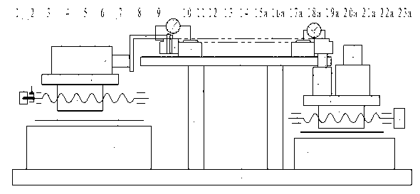
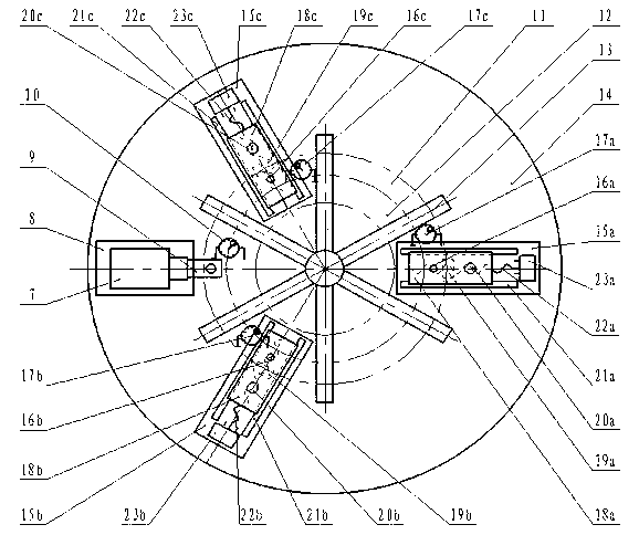
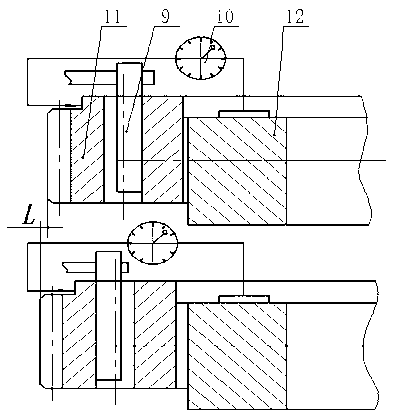
[0017] When the slewing bearing to be tested is an external gear type, first place the slewing bearing to be tested on the detection workbench 13, and the controller drives the first axial servo motor 23a, the second axial servo motor 23b, and the third axial servo motor. The servo motor 23c rotates at the same time, respectively driving the first centering mechanism 20a, the second centering mechanism 20b, and the third centering mechanism 20c to move in the radial direction simultaneously to complete the centering of the inner ring 12 of the slewing bearing to be tested, and then through the screw platen The clamping mechanism fixes the inner ring 12 of the slewing ring to be tested on the detection workbench 13, and at this time, the outer ring 11 of the slewing ring to be tested naturally sags under the action of its own weight. Fix the fixed end of the axial displacement sensor 17 on the upper surface of the inner ring 12 o...

Embodiment 2

[0019] Embodiment 2: Detection of Radial Clearance

[0020]When the slewing bearing to be tested is an external gear type, first place the slewing bearing to be tested on the detection workbench 13, and the controller drives the first axial servo motor 23a, the second axial servo motor 23b, and the third axial servo motor. The servo motor 23c rotates at the same time, and respectively drives the first centering mechanism 20a, the second centering mechanism 20b, and the third centering mechanism 20c to move simultaneously in the radial direction to complete the centering of the inner ring 12 of the slewing bearing to be tested, and then through the screw platen The clamping mechanism fixes the inner ring 12 of the slewing bearing to be tested on the testing workbench 13 . The radial servo motor 1 is driven by the controller, and when the radial worktable 6 is driven by the radial ball screw 3 and the radial screw nut 5 to move to the detection position on the radial rolling gui...


PUM


Abstract

The invention provides a gap detection device of a large slewing bearing and belongs to the technical field of industrial measurement. The gap detection device comprises a radial error detection table, three groups of symmetrically-distributed axial error detection tables, a detection working table frame with a spiral pressing plate clamping mechanism, a slewing bearing to be detected, a controller and a displayer. Each axial error detection table comprises an axial servo motor, an axial rolling guide rail, an axial ball screw, a centering mechanism, an axial screw nut, an axial servo electric pushing rod, an axial working table plate, an axial base and an axial displacement sensor. The radial error detection table comprises a radial servo motor, a locking mechanism, a radial ball screw, a radial rolling guide rail, a radial screw nut, a radial working table plate, a radial servo electric pushing rod, a fork head, a radial base and a radial displacement sensor. The gap detection device of the large slewing bearing has the advantages of being high in detection accuracy, convenient to operate and high in detection efficiency.

Description

technical field [0001] The invention belongs to the technical field of industrial measurement, and in particular relates to a large-scale slewing bearing clearance detection device, which is used for detecting the axial and radial clearances of the installed inner and outer rings of the large-diameter slewing support. Background technique [0002] The axial and radial clearance detection between the inner and outer rings of large slewing bearings has always been a major problem in the industry. At present, the traditional manual detection method is often used: for axial clearance detection, the specific method is to place the slewing bearing on a working platform, and several inspectors use the crowbar to pry the different fulcrums of the inner ring (or outer ring) of the slewing ring at the same time , and then use the dial indicator to measure the height difference at different positions of the end faces of the inner and outer rings of the slewing bearing, and take the ave...

Claims


Application Information

Patent Timeline
IPC IPC(8): G01B21/16
Inventor 余晓流汪永明谈莉斌汪丽芳王全先刘庆运汪叶青余云霓戴克芳
Owner ANHUI UNIVERSITY OF TECHNOLOGY
Why Eureka
Try Eureka