Sensing device, power reception device, power transmission device, non-contact power transmission system, and sensing method

A technology of power transmission and power reception, which is applied in the field of detection devices, can solve problems such as heat generation, and achieve the effect of improving detection accuracy

Inactive Publication Date: 2013-03-27
SONY CORP
View PDF4 Cites 41 Cited by
  • Summary
  • Abstract
  • Description
  • Claims
  • Application Information

AI Technical Summary

Problems solved by technology

The problem is that if there is metal between the power transmitting side and the power receiving side when performing non-contact power supply, heat is generated due to eddy currents generated in the metal

Method used


Image

  • Sensing device, power reception device, power transmission device, non-contact power transmission system, and sensing method
  • Sensing device, power reception device, power transmission device, non-contact power transmission system, and sensing method
  • Sensing device, power reception device, power transmission device, non-contact power transmission system, and sensing method

Examples


Embodiment approach

[0033] [introductory description]

[0034] The metal foreign object detection technology in the present disclosure is a technology for detecting metal foreign objects using the above-mentioned change in the Q value. The Q value is an index representing the relationship between energy retention and loss. Usually, the Q value is used to identify the sharpness of the resonant peak of the resonant circuit. The metallic foreign matter is a conductor such as metal between the power transmitting side (primary side) and the power receiving side (secondary side). The term conductor may also include conductors in the broad sense, ie, semiconductors.

[0035] [Q value measurement principle]

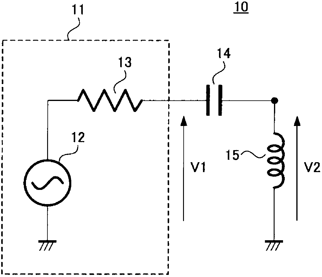
[0036] Here, will refer to figure 1 The principle of Q-value measurement is described.

[0037] figure 1 is a schematic circuit diagram showing Q value measurement performed in a contactless power transmission system.

[0038] figure 1 The circuit of the power transmission device 10 shown is...


PUM


Abstract

The invention provides a sensing device, a power reception device,a power transmission device, a non-contact power transmission system, and a sensing method, wherein the sensing device includes a circuit including at least a coil electromagnetically coupled to an outside; a temperature detection unit for detecting a temperature of the coil; a sensing unit for measuring a Q value of the circuit; and a correction unit for correcting the Q value measured by the sensing unit based on temperature information detected by the temperature detection unit.

Description

technical field [0001] The present disclosure relates to a detection device, a power reception device, a power transmission device, a non-contact power transmission system, and a detection method for detecting the presence of a conductor such as metal. Background technique [0002] Recently, a non-contact power transmission system that provides (wirelessly transmits) power in a non-contact method has been actively developed. There are roughly two types of technologies in a method of realizing wireless power supply. [0003] One technique is the well known electromagnetic induction scheme. In the electromagnetic induction scheme, the degree of coupling between the power transmitting side and the power receiving side is very high and power can be efficiently supplied. However, because it is necessary to maintain a high coupling coefficient between the power transmitting side and the power receiving side, if the power transmitting side is far from the power receiving side or ...

Claims


Application Information

Patent Timeline
Patent Type & Authority Applications(China)
IPC IPC(8): G01V3/10H02J17/00G01R31/72
CPCG01R27/28G01R31/06G01R31/42G01R31/72H02J50/12H02J50/60G01R31/346
Inventor 中野裕章村上知伦小堺修藤卷健一
Owner SONY CORP
Why Eureka
Try Eureka