

Camera system and interchangeable lens
A camera and lens technology, applied in the direction of cameras, camera bodies, camera focusing devices, etc., can solve the problems of image quality damage, high pressure, unnatural focus changes, etc., to achieve the effect of improving operability
- Summary
- Abstract
- Description
- Claims
- Application Information
AI Technical Summary
Problems solved by technology
Method used
Image

Examples
Embodiment approach 1
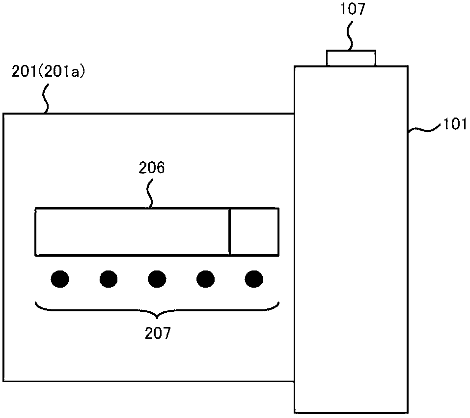
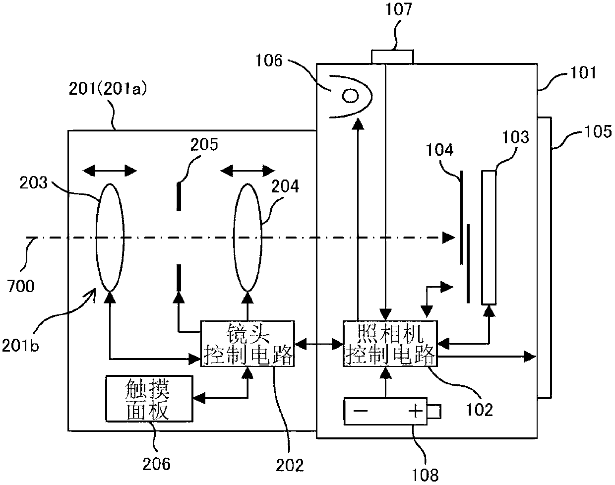
[0055] figure 1 It is a schematic diagram of the side appearance of the camera system in which the interchangeable lens according to Embodiment 1 of the present invention is attached to the camera body. The camera system 100 according to Embodiment 1 includes a camera body 101 and an interchangeable lens 201 attached to the camera body 101 so that a lens can be interchanged. A release button 107 is provided on the upper surface of the camera body 101 . In addition, in the interchangeable lens 201, a touch panel 206 (touch panel) (contact position detection unit) and an indicator arranged corresponding to the touch panel 206 are provided on the side surface of the lens barrel 201a accommodating an optical system 201b (optical system) described later. 207 (Identification). In addition, in the following figure 2 The camera body 101, the release button 107, the interchangeable lens 201, the touch panel 206, and the like are described in detail in . In Embodiment 1, as will be...
Embodiment approach 2
[0092] In this second embodiment, an example in which a change operation of shooting settings such as an AF mode and a shutter speed is performed by a touch operation of the touch panel 206 of the interchangeable lens 201 will be described.
[0093] The basic structure and photographing operation of the interchangeable lens 201 and the camera body 101 according to Embodiment 2 are the same as those described above. figure 2 as well as image 3 It is the same as Embodiment 1 exemplified.
[0094] with the above Figure 6 , Figure 7A as well as Figure 7B It is the same as Embodiment 1 exemplified.
[0095] Figure 13 It is a diagram showing an example of a touch panel display of an interchangeable lens according to Embodiment 2 of the present invention.
[0096] in the Figure 13 3 shows various display examples in the operation mode display area 206 a (second area) and the operation mode setting value display area 206 b (first area) on the touch panel 206 .
[0097] ...
Embodiment approach 3
[0140]In Embodiment 3, during the operation of the touch panel 206 of the interchangeable lens 201, the touch position of the finger is detected two-dimensionally, an operation mode is selected at the touch position in the vertical direction (circumferential direction of the lens barrel 201a), and an operation mode is selected in the horizontal direction (circumferential direction of the lens barrel 201a). Lens operation is performed by sequentially selecting setting values at the touch position of the barrel 201a along the optical axis direction. The basic structure and photographing operation of the interchangeable lens 201 and the camera body 101 according to Embodiment 3 are the same as those described above. figure 2 as well as image 3 It is the same as Embodiment 1 exemplified. Figure 18 It is a diagram showing an example of a touch position detection area and a display of an interchangeable lens touch panel according to Embodiment 3 of the present invention. The ...
PUM
 Abstract
Description
Claims
Application Information