Exposure apparatus

An exposure device and laser technology, which is applied in the direction of photolithographic process exposure device, printing device, microlithography exposure equipment, etc., can solve the problems of inability to perform exposure and inability to detect the extent to which the mobile platform 32 has moved

Active Publication Date: 2013-03-27
USHIO DENKI KK
View PDF7 Cites 6 Cited by
  • Summary
  • Abstract
  • Description
  • Claims
  • Application Information

AI Technical Summary

Problems solved by technology

[0028] (6) In the above, although the alignment of the mask M and the workpiece W is completed, and then shifts to the exposure process, however, exposure cannot be performed in this state
[0035] For this reason, as described above, when the movable stage 32 moves in the direction of the optical axis L of the pro

Method used


Image

  • Exposure apparatus
  • Exposure apparatus
  • Exposure apparatus

Examples


Example Embodiment

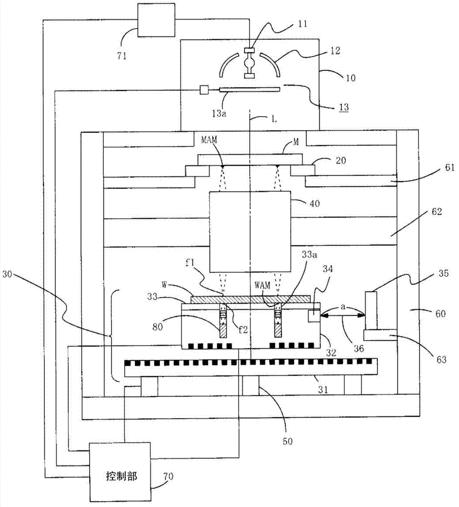
[0088] figure 1 A configuration example of an exposure apparatus according to an embodiment of the present invention is shown. This figure shows the projection exposure apparatus which exposes the workpiece|work in which the alignment mark was formed in the back surface of a workpiece|work similarly to the said conventional example.

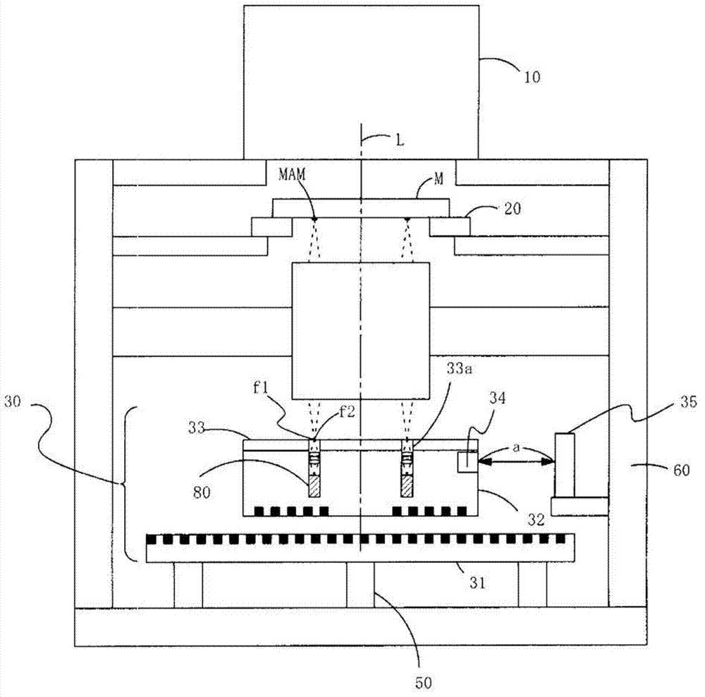
[0089] The exposure apparatus of this embodiment and Image 6 The shown devices are the same, and mainly include: a light irradiation unit 10; a mask M for forming a pattern exposed (transferred) to a workpiece; a mask table 20 for holding the mask M; and a printed circuit board for holding the exposure process. or a work stage 30 of a work W such as a liquid crystal panel;

[0090] In addition, as a projection member, there may be a member using a mirror instead of a projection lens or a lens using a lens, but in this embodiment, the projection lens 40 will be described as an example. As for the way of projecting means, whether it is a means ...


PUM


Abstract

An exposure apparatus of the present invention contains: a moving stage that includes a laser length measuring device, the laser length measuring device is configured to emit and receive a laser light; an XY[theta] direction moving mechanism configured to move the moving stage within a plane; a Z direction moving mechanism configured to move the moving stage and the XY[theta] direction moving mechanism in a direction perpendicular to the plane; a reflective mirror that is configured to reflect the laser light, the laser length measuring device is configured to measure a distance between the laser length measuring device and the reflection mirror; and a control unit configured to control the XY[theta] direction moving mechanism to move the moving stage based on the distance. Since the mirror, which reflects laser from the laser length measuring device provided on the moving stage of the work stage, is integrally fixed to the structural body, which supports the mask stage for holding a mask, when the work stage is moved in the Z direction (a direction perpendicular to the workpiece face), even if the moving stage is moved in the XY direction (direction parallel to the workpiece face), and in the [theta] direction (a rotation direction with respect to an axis perpendicular to the workpiece face), the reflective mirror does not shift. Therefore, when the work stage is moved in the Z direction, even if a slider is moved in the XY direction or the e direction, it is possible to detect the amount of movement thereof by the laser length measuring device. For this reason, the moving stage is moved so that the detected amount of movement may be canceled, whereby the workpiece can be returned to the original position (a position where the position of the mask and that of the workpiece are aligned).

Description

technical field [0001] The present invention relates to an exposure apparatus, and more specifically, to an exposure apparatus capable of reducing the amount of positional displacement on the table top of a mobile table that occurs when the mobile table is moved in a direction perpendicular to the table top. Background technique [0002] The exposure apparatus is used for pattern formation of wiring etc. in the manufacturing process of a printed circuit board, a liquid crystal panel, etc. (hereinafter also referred to as a workpiece). exist Image 6 A configuration example of the above-mentioned exposure apparatus is shown in . [0003] Image 6 The exposure apparatus shown is a projection exposure apparatus equipped with a projection lens for exposing a workpiece by projecting a pattern of a mask on the projection lens. The apparatus shown in this figure shows a projection exposure apparatus that forms The alignment mark is exposed by aligning the alignment mark (hereinaft...

Claims


Application Information

Patent Timeline
IPC IPC(8): G03F7/20
CPCG03B27/58G03F7/70725G03F7/70775G03F9/7015G03F9/7084G03F9/7088G03B27/16G03F7/20H01L21/0273H01L21/68
Inventor 杉山茂久
Owner USHIO DENKI KK
Why Eureka
Try Eureka