LED (light-emitting diode) spliced screen module box

A splicing screen and module technology, which is applied in the direction of cabinet/cabinet/drawer parts, instruments, identification devices, etc., can solve the problems of cumbersome splicing screen construction process, time-consuming and labor-consuming, low operation efficiency, etc., to achieve Save labor costs and time costs, improve implementation efficiency, and speed up installation

Inactive Publication Date: 2013-03-27
成卓
View PDF5 Cites 17 Cited by
  • Summary
  • Abstract
  • Description
  • Claims
  • Application Information

AI Technical Summary

Problems solved by technology

Existing LED splicing screens are generally composed of multiple LED splicing screen module boxes. The current LED splicing screen module boxes are generally installed by screws and nuts when splicing to achieve splicing. However, due to LED splicing screens are generally rectangular or square modules. When splicing, four sides need to be fixed, and each side needs to be fixed with multiple screws. Therefore, when the entire large screen is combined, a large number of screws and screws need to be installed. Caps, not only need to prepare more and scattered accessories, but also require a lot of installation work during the overall assembly, which is time-consuming and labor-intensive, and the operation efficiency is low. The construction process of becoming a splicing screen is relatively cumbersome.

Method used


Image

  • LED (light-emitting diode) spliced screen module box
  • LED (light-emitting diode) spliced screen module box

Examples


Embodiment Construction

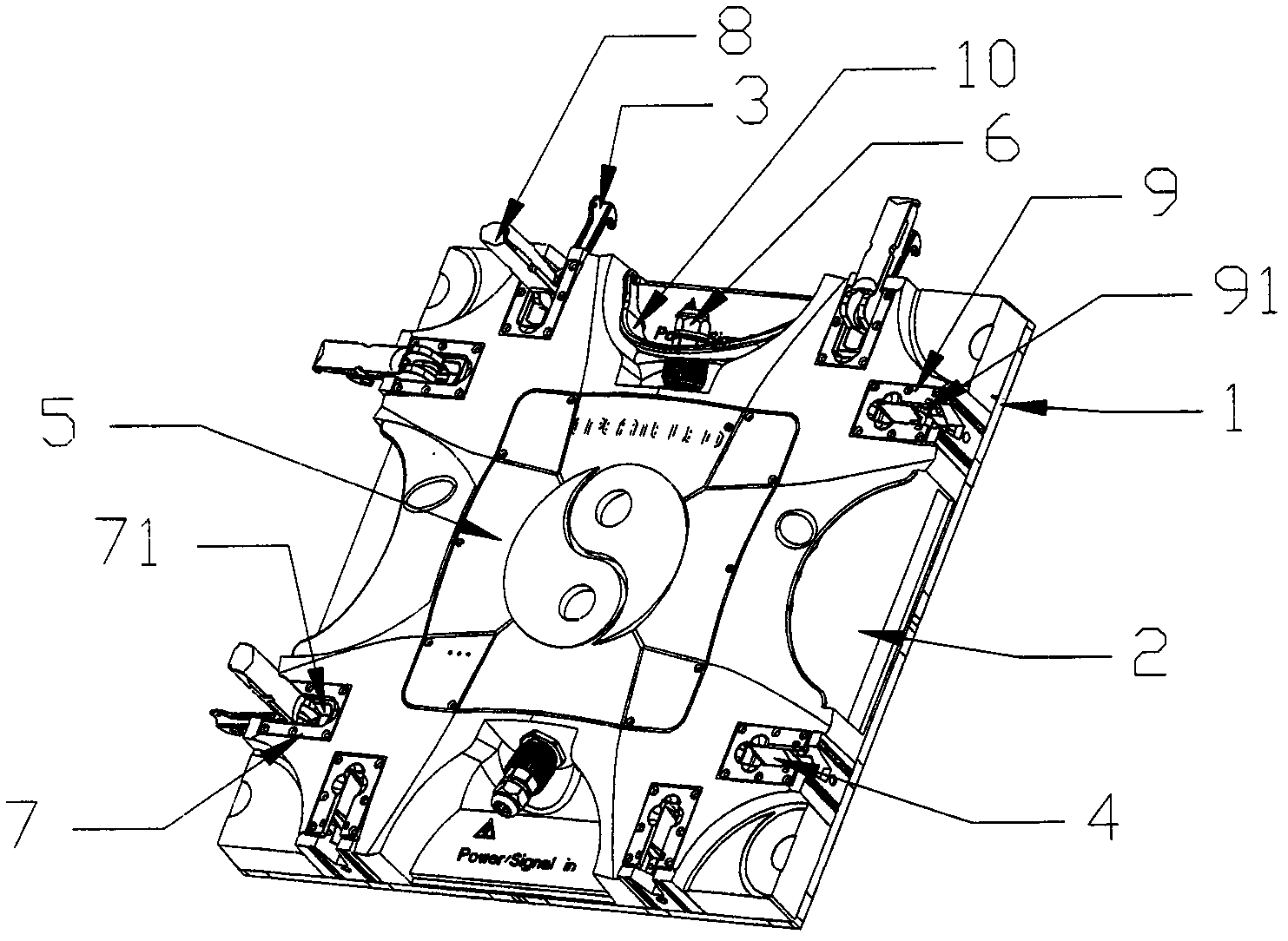
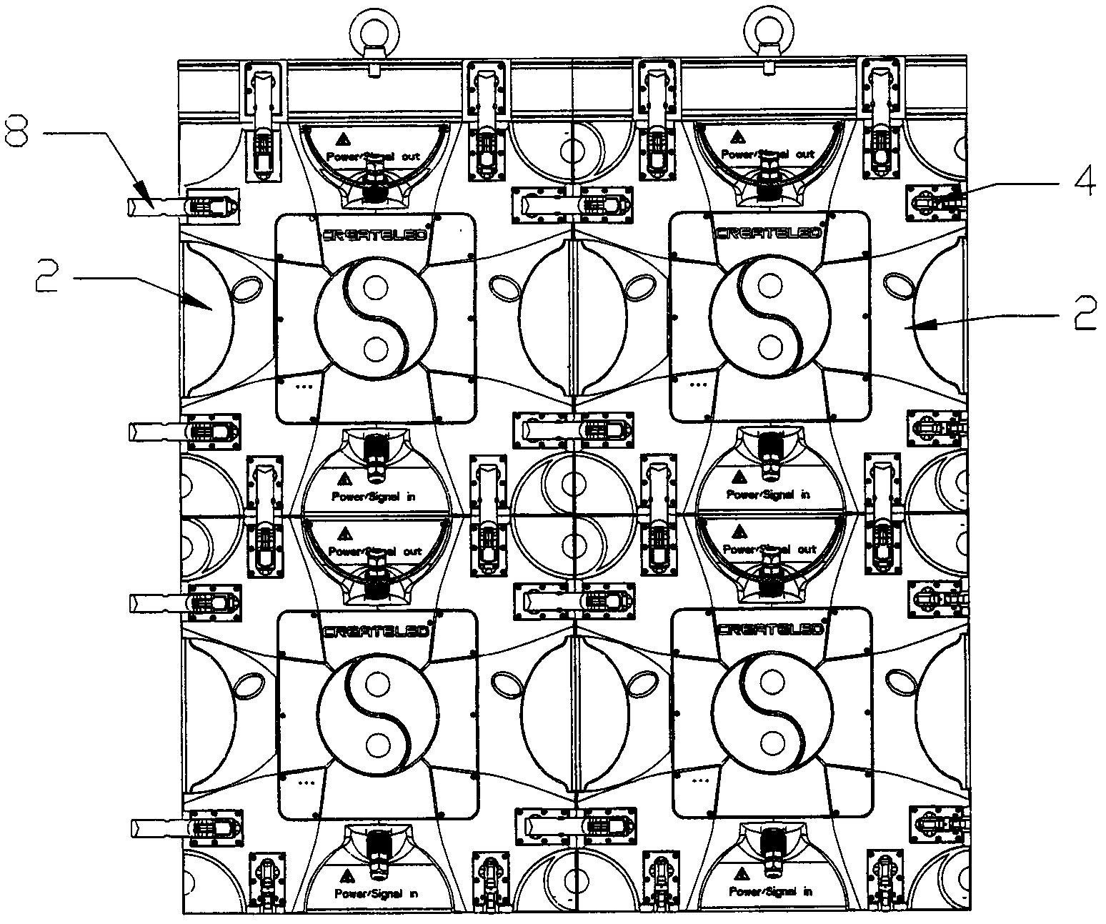
[0015] Such as figure 1 and figure 2 As shown, the LED splicing screen module box in this embodiment includes a rectangular or square panel 1 and a main box 2, the main box 2 is arranged behind the panel 1, and each side of the main box 2 There are lock hooks 3 and / or lock grooves 4 for the lock hooks 3 to fasten, and the lock hooks 3 and lock grooves 4 on the opposite two sides are arranged oppositely. The locking hooks 3 and the locking grooves 4 have the same number and the same positions.

[0016] In this embodiment, for the convenience of installation, multiple locking hooks 3 are provided on two adjacent sides of the main box body 2 , and locking grooves corresponding to the positions of the locking hooks are provided on the other two adjacent sides.

[0017] Specifically, the middle part of the main box body 2 is provided with a cavity for installing a power supply, a rear cover 5 is provided on the cavity, and a connector 6 is provided beside the cavity.

[0018] T...


PUM


Abstract

The invention relates to an LED (light-emitting diode) spliced screen, in particular to an LED spliced screen module box which is easy to splice and combine. The LED spliced screen module box comprises a rectangular or square panel and a main box body. The main box body is arranged behind the panel. Lock hooks and / or lock grooves for fastening the lock hooks are arranged on each side of the main box body. The lock hooks and the lock grooves on opposite two sides are oppositely arranged. By adopting a matched installation structure with the lock hooks and the lock grooves instead of the traditional matched installation structure with screws and nuts, during installation, the lock hooks are only required to be placed and fastened in the lock grooves, then the combination and the splicing of LED spliced screen module boxes can be realized, the LED spliced screen module box is convenient to install, tools such as screw drivers are not required, the implementation efficiency of splicing operation is improved, the installation speed of the entire spliced screen is accelerated, and the labor cost and the time cost are saved.

Description

technical field [0001] The invention relates to an LED splicing screen, in particular to an LED splicing screen module box which is easy to splice and combine. technical background [0002] Due to the combination of LED screens in the form of splicing, they can form display screens of any size. Due to this feature, the existing LED screens have been widely used in outdoor screen walls, indoor and outdoor stadiums, airport stations, traffic instructions, etc. , used to display advertisements, race results, train number information, and traffic conditions. Existing LED splicing screens are generally composed of multiple LED splicing screen module boxes. The current LED splicing screen module boxes are generally installed by screws and nuts when splicing to achieve splicing. However, due to LED splicing screens are generally rectangular or square modules. When splicing, four sides need to be fixed, and each side needs to be fixed with multiple screws. Therefore, when the entir...

Claims


Application Information

Patent Timeline
Patent Type & Authority Applications(China)
IPC IPC(8): G09F9/33H05K5/02
CPCG09F9/3026
Inventor 贺理张大有
Owner 成卓
Why Eureka
Try Eureka