Flywheel energy storage system

A flywheel energy storage and flywheel technology, which is applied in the field of flywheel energy storage systems, can solve the problems of reducing flywheel standby time, high investment cost, and large occupied volume, and achieves the effect of long flywheel standby time, low investment cost, and small occupied volume.

Inactive Publication Date: 2013-03-27
汤镛之
View PDF7 Cites 2 Cited by
  • Summary
  • Abstract
  • Description
  • Claims
  • Application Information

AI Technical Summary

Problems solved by technology

[0002] At present, in the field of flywheel energy storage technology, motors and flywheels are needed, and the motors involved require expensive rare earth permanent magnet materials, which greatly increases the cost of flywheel energy storage; moreover, the electromagnetic eddy current loss and magnetic Hysteresis loss reduces system efficiency and greatly reduces flywheel standby time
In addition, the volume occupied by the motor and flywheel is large, which also increases the cost
[0003] In the process of realizing the present invention, the inventors found that there are at least some defects in the prior art, such as large occupied volume, high investment cost, low system efficiency and short standby time of the flywheel.

Method used


Image

  • Flywheel energy storage system

Examples


Embodiment Construction

[0016] The preferred embodiments of the present invention will be described below in conjunction with the accompanying drawings. It should be understood that the preferred embodiments described here are only used to illustrate and explain the present invention, and are not intended to limit the present invention.

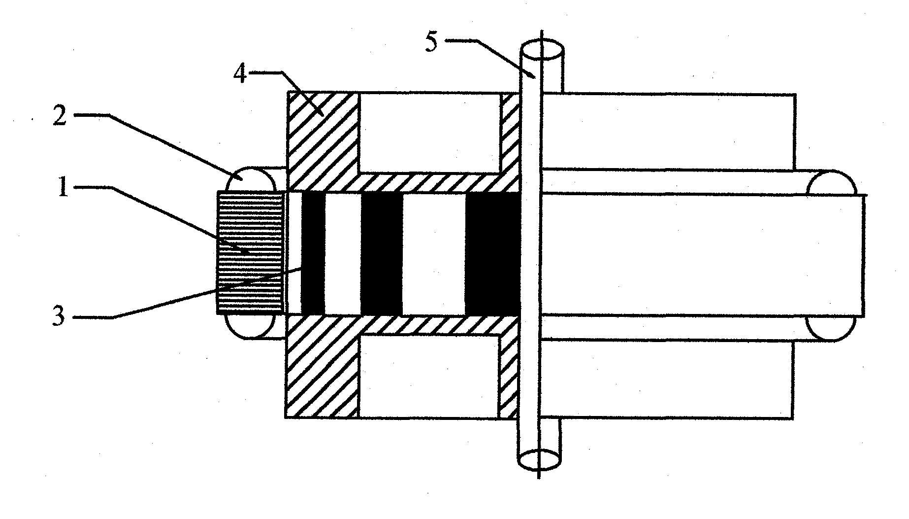
[0017] According to an embodiment of the present invention, a flywheel energy storage system is provided, that is, a flywheel energy storage-power generation system driven by a high-speed switched reluctance motor with large inertia and high speed. Such as figure 1 As shown, the present embodiment includes a disc-shaped reluctance motor (i.e. a high-speed switched reluctance motor), a flywheel (such as flywheel 4) that is installed on a vertically arranged shaft and is used to store energy, and a flywheel with a flywheel. The shaft (such as the shaft 5) cooperates with the magnetic suspension bearing arranged. The shaft is installed on the magnetic levitation beari...


PUM


Abstract

The invention discloses a flywheel energy storage system. The flywheel energy storage system comprises a magnetic resistance motor of a disk-shaped structure, a vertically arranged shaft, a flywheel and a magnetic levitation bearing, wherein the flywheel is mounted on the magnetic resistance motor and the shaft in a matched manner and is used for storing energy, and the magnetic levitation bearing is matched with the shaft. The flywheel energy storage system can overcome the defects of large occupied size, high input cost, low system efficiency, short flywheel standby time and the like of the prior art and has the advantages of small occupied size, low input cost, high system efficiency and long flywheel standby time.

Description

technical field [0001] The present invention relates to the technical field of electric power storage and inverter power generation, in particular to a flywheel energy storage system. Background technique [0002] At present, in the field of flywheel energy storage technology, motors and flywheels are needed, and the motors involved require expensive rare earth permanent magnet materials, which greatly increases the cost of flywheel energy storage; moreover, the electromagnetic eddy current loss and magnetic The hysteresis loss reduces the system efficiency and greatly reduces the standby time of the flywheel. In addition, the volume occupied by the motor and the flywheel is large, which also increases the cost. [0003] In the process of realizing the present invention, the inventors found that the prior art at least has defects such as large occupied volume, high investment cost, low system efficiency and short standby time of the flywheel. Contents of the invention ...

Claims


Application Information

Patent Timeline
Patent Type & Authority Applications(China)
IPC IPC(8): H02K7/02
CPCY02E60/16
Inventor 汤镛之
Owner 汤镛之
Why Eureka
Try Eureka