Temperature compensation method and crystal oscillator

A technology of crystal oscillators and crystal oscillations, applied in power oscillators, electrical components, output stabilization, etc., can solve problems such as time and production cost impacts, and achieve low-cost effects

Active Publication Date: 2013-03-27
HUAWEI TECH CO LTD
View PDF3 Cites 27 Cited by
  • Summary
  • Abstract
  • Description
  • Claims
  • Application Information

AI Technical Summary

Problems solved by technology

However, in large-scale applications, each temperature sensor has discreteness, and the temperature-frequency curve of the crystal oscillator also has discreteness, and they need to be calibrated. This kind of calibration in a wide temperature range has a great impact on the time and Production costs have a major impact

Method used


Image

  • Temperature compensation method and crystal oscillator
  • Temperature compensation method and crystal oscillator
  • Temperature compensation method and crystal oscillator

Examples


Embodiment Construction

[0019] The following will clearly and completely describe the technical solutions in the embodiments of the present invention with reference to the accompanying drawings in the embodiments of the present invention. Obviously, the described embodiments are some of the embodiments of the present invention, but not all of them. Based on the embodiments of the present invention, all other embodiments obtained by persons of ordinary skill in the art without making creative efforts belong to the protection scope of the present invention.

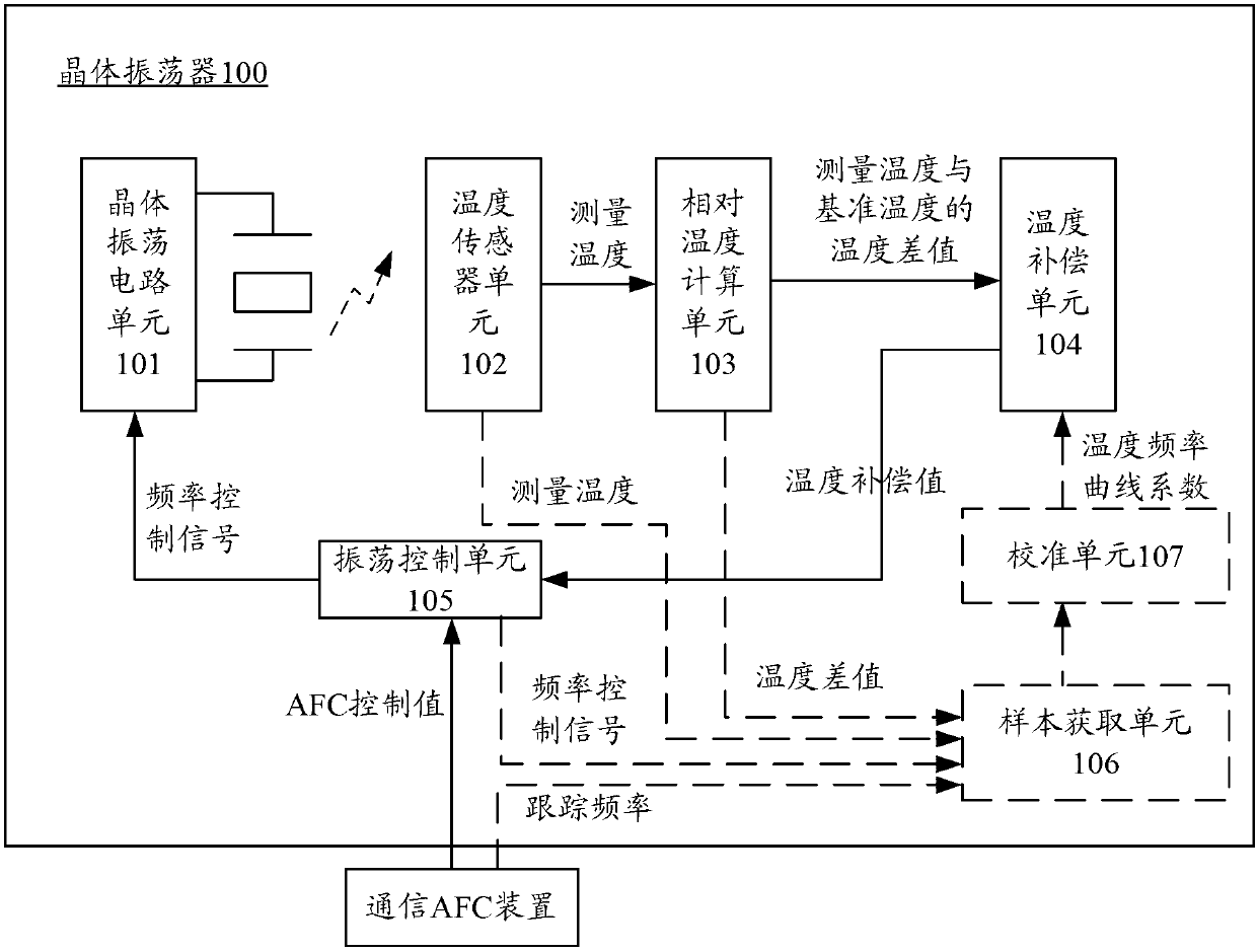
[0020] figure 1 is a schematic structural diagram of a crystal oscillator 100 according to an embodiment of the present invention. The crystal oscillator 100 may include a crystal oscillation circuit unit 101 , a temperature sensor unit 102 , a relative temperature calculation unit 103 , a temperature compensation unit 104 and an oscillation control unit 105 .

[0021] The temperature sensor unit 102 can measure the measurement temperature of the...


PUM


Abstract

The embodiment of the invention provides a temperature compensation method and a crystal oscillator. The crystal oscillator comprises a crystal oscillation circuit unit, a temperature sensor unit, an oscillation control unit, a relative temperature calculating unit and a temperature compensation unit. The temperature sensor unit is used for measuring the measurement temperature of the crystal oscillation circuit unit; the relative temperature calculating unit is used for obtaining the temperature difference value between the measurement temperature and a reference temperature; the temperature compensation unit is used for obtaining a temperature compensation value corresponding to the temperature difference value from a temperature frequency curve; and the oscillation control unit is used for generating a frequency control signal according to tracking frequency of a communication AFC (Automatic Frequency Control) device and the temperature compensation value so as to control the frequency of the crystal oscillation circuit unit to work on the tracking frequency. In the embodiment of the invention, the temperature compensation value is determined by obtaining the temperature difference value between the measurement temperature and the reference temperature according to the temperature difference value and the coefficients of the temperature frequency curve, so that better temperature compensation results are obtained with relatively low cost.

Description

technical field [0001] Embodiments of the present invention relate to the technical field of electronic devices, and more specifically, relate to a temperature compensation method and a crystal oscillator. Background technique [0002] An existing temperature compensation oscillator system solution is composed of a crystal oscillator module, a temperature sensor module, a temperature compensation processing module and an oscillator control module. The crystal oscillator module is composed of an oscillator module and a crystal. [0003] In the temperature sensor module near the quartz crystal, the thermistor with negative temperature coefficient senses the temperature change, converts it into a voltage signal, and then converts it into a digital signal in the temperature sensor module; the temperature signal in digital form is input to the temperature compensation module, and the temperature compensation According to the temperature-frequency curve of the crystal oscillator ...

Claims


Application Information

Patent Timeline
Patent Type & Authority Applications(China)
IPC IPC(8): H03B5/04H03B5/32
CPCH03L1/02H03L1/022H03B5/04H03B5/36H03B5/364H03L1/027H03L1/04
Inventor 张强
Owner HUAWEI TECH CO LTD
Why Eureka
Try Eureka