

Acoustic receiving device
A sound receiving and microphone technology, applied in the field of sound processing, can solve problems such as poor angle, reduced output gain, complexity of regulation and debugging, etc., and achieve the effect of simple structure and improved output gain
- Summary
- Abstract
- Description
- Claims
- Application Information
AI Technical Summary
Problems solved by technology
Method used
Image


Examples
Embodiment Construction
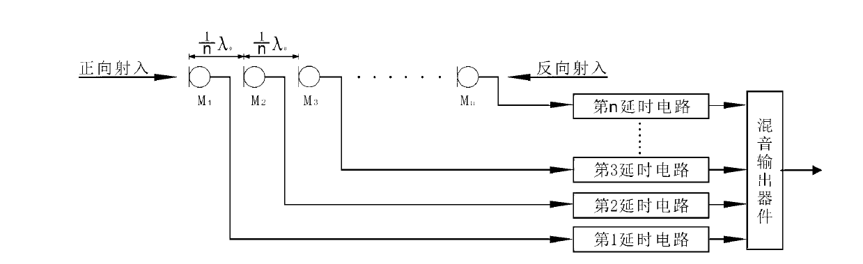
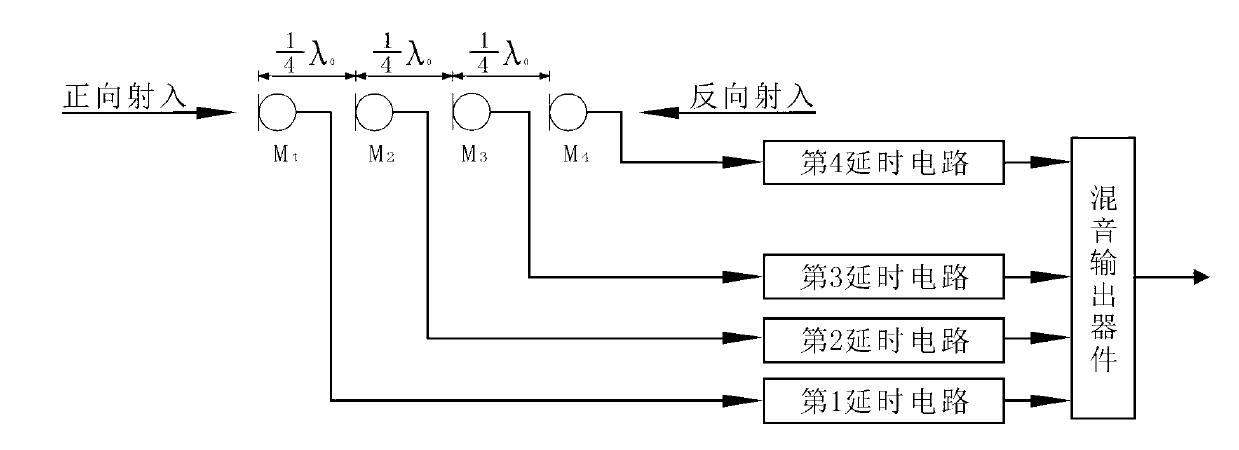
[0020] Depend on figure 1 As shown, a sound receiving device includes a microphone array, a delay circuit and a mixing output device, and the microphone array includes a plurality of microphones, such as figure 1 As shown, the multiple microphones are M 1 , M 2 , M 3 ... M n , and the frequency response, sensitivity, and directivity characteristics of each microphone are basically the same;
[0021] The plurality of microphones M 1 , M 2 , M 3 ... M n Arranged vertically along a straight line, the distance between two adjacent microphones in the microphone array is That is, the spacing distance between two adjacent microphones in the microphone array is equal, and the spacing distance is where n is the total number of microphones in the microphone array, λ 0 is the wavelength derived from the set center frequency, and λ 0 The calculation formula is as follows:
[0022] λ 0 = C ...
PUM
 Abstract
Description
Claims
Application Information