Radio network communication system and data transmission method thereof
A technology of communication system and wireless network, which is applied in the field of wireless network communication system and its data transmission, and can solve problems such as numerous interfaces, low resource utilization rate, and too many system layers
- Summary
- Abstract
- Description
- Claims
- Application Information
AI Technical Summary
Problems solved by technology
Method used
Image

Examples
Embodiment 1
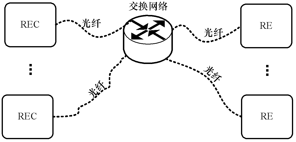
[0026] The structure of a flat wireless network communication system proposed in this embodiment is as follows figure 2 Shown in figure 2 In the wireless network communication system shown, the entire network structure simplifies the network hierarchy. RECs, REs and switching networks are connected to each other through optical fibers. One REC manages at least one RE, and one RE belongs to one REC. , The REC and the RE, and the RECs communicate with each other through the switching network. It is understandable that, if necessary, the REs can also directly communicate with each other through the switching network.
[0027] The number of RECs and REs can be multiple, and multiple RECs can be centrally placed in geographically close places, or multiple RECs can be dispersedly placed in geographically distant places.
[0028] The switching network may be a ring-shaped metropolitan area network composed of at least one switch based on MAC (Medium Access Control) layer or IP (Internet...
Embodiment 2
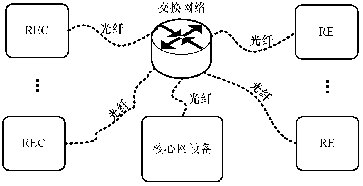
[0053] In the embodiment of the present invention, the REC, RE, and the switching network are connected to each other through optical fiber, one REC manages at least one RE, and one RE belongs to one REC management, and the REC and the RE, and the RECs in pairs communicate with each other through the switching network. Between communication.
[0054] Further, the core network equipment and the REC, RE, and the switching network are connected through optical fibers, and the core network equipment and the REC, and the core network equipment and the RE communicate with each other through the switching network.
[0055] The RE needs to register with the REC. The RE sends an access request carrying the MAC address of the RE to the REC through the switching network, and the REC obtains and saves the MAC address of the RE carried in the access request. The RE constructs a MAC frame that carries a message type field, and the message type field includes the RE's identifier, MAC address, and...
Embodiment 3
[0090] When REC and RE need to transmit data frames to other nodes, the above-mentioned REC and RE send data to the switching network through optical fiber, and the switching network transmits the data to the core network equipment, and the core network equipment transmits the data to the switching network. Destination node. After the switching network has established a complete address table through learning, REC and RE can directly transmit data through the switching network.
[0091] This embodiment provides a schematic diagram of the flow of REC transferring data to RE0, such as Picture 11 As shown, the specific processing process is as follows:
[0092] The application layer of REC passes the data to the MAC layer of REC, and the MAC layer of REC searches the MAC address table saved by REC to obtain the MAC address of RE0.
[0093] The MAC layer of REC composes a MAC frame based on the MAC address and data content of RE0. The structure of the MAC frame is shown in Table 5 bel...
PUM
 Abstract
Description
Claims
Application Information
 - R&D
- Intellectual Property
- Life Sciences
- Materials
- Tech Scout
- Unparalleled Data Quality
- Higher Quality Content
- 60% Fewer Hallucinations
Browse by: Latest US Patents, China's latest patents, Technical Efficacy Thesaurus, Application Domain, Technology Topic, Popular Technical Reports.
© 2025 PatSnap. All rights reserved.Legal|Privacy policy|Modern Slavery Act Transparency Statement|Sitemap|About US| Contact US: help@patsnap.com