Magnetism column pin roller

A magnetic column and roller technology, applied in the field of roller presses, can solve the problems of reducing the surface protection of the roller body, reducing the grinding efficiency of the roller press, affecting the overall life of the rollers, etc., so as to reduce equipment maintenance costs and improve equipment operation efficiency. , to ensure the effect of grinding efficiency

Inactive Publication Date: 2013-04-03
CHENGDU LEEJUN IND
View PDF10 Cites 4 Cited by
  • Summary
  • Abstract
  • Description
  • Claims
  • Application Information

AI Technical Summary

Problems solved by technology

However, in the actual production process, especially when the water content of the material is high, the pad between the studs often slips due to being squeezed, exposing the surface of the roller body, reducing the protection of the surface of the roller body, resulting in a The situation that the nails have not been worn out but the surface of the roller body is severely worn will seriously affect the overall life of the roller and reduce the grinding efficiency of the roller press

Method used


Image

  • Magnetism column pin roller
  • Magnetism column pin roller

Examples


Embodiment 1

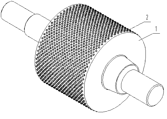
[0024] Embodiment 1, the magnetic stud 2 roller of the present invention comprises a magnetic roller body and a stud 2, and several studs 2 are evenly distributed on the surface of the magnetic roller body, wherein the stud 2 is made of hard alloy, and the magnetic roller body is made of It is made of magnetized hard magnetic materials (such as: rare earth permanent magnet materials, metal permanent magnet materials, ferrite permanent magnet materials, etc.), so that the roller body can evenly absorb the magnetic materials to form a material pad, and when the material pad is squeezed and slips When it is used, it has the function of automatically filling and forming a material pad. The magnetic strength of the magnetic roller body is 500 Gs, 1500 Gs or 2500 Gs, which can be set arbitrarily between 500-2500 Gs.

Embodiment 2

[0025] Embodiment 2 is similar to Embodiment 1, except that: the magnetic roller body and stud 2 are made of hard magnetic materials (such as rare earth permanent magnet materials, metal permanent magnet materials, ferrite permanent magnet materials, etc.) Made, so that the roller body and the stud 2 can evenly absorb the magnetic material to form a material pad, so that the material pad is less likely to be squeezed, even if it is squeezed and slipped, it can be quickly replenished by the newly passed magnetic material to form a complete The material pad, in which the magnetic field strength is 1000Gs or 2000Gs, can be set arbitrarily between 500-2500Gs.

Embodiment 3

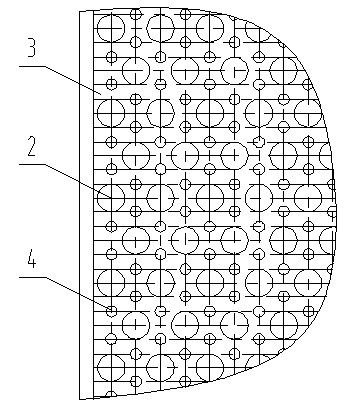
[0026]Embodiment 3 is similar to Embodiment 1, and its difference is: the magnetic roller body adopts the soft magnetic material (soft magnetic material is the material that when magnetization occurs at Hc not greater than 1000A / m, including pure iron and low carbon steel, iron-silicon alloy, iron-aluminum alloy, iron-silicon-aluminum alloy, soft ferrite, etc.), such as figure 2 As shown, the magnets 4 are evenly distributed on the surface of the roller body between the studs 2, so that the magnetic material can be evenly adsorbed on the surface of the roller body, so that the formed material pad is uniform, thereby realizing the protection of the roller body. Among them, the magnetic strength is 800 Gs, 1200 Gs or 1800 Gs or 2200Gs, which can be set arbitrarily between 500-2500Gs. In this example, the stud 2 can be selected to be made of a hard magnetic material according to actual needs, so that the stud 2 and the magnet 4 uniformly distributed on the surface of the roller ...


PUM


Abstract

The invention discloses a magnetism column pin roller, and belongs to the technical field of roller grinding equipment. The magnetism column pin roller provided by the invention comprises a magnetism roller body and column pins, and the plurality of column pins are uniformly distributed on the surface of the magnetism roller body. Through the magnetism column pin roller provided by the invention, materials form a material gasket automatically on the surface of the roller body, meanwhile, materials with magnetism also are absorbed on the surface of the roller body among the column pins so as to form a material gasket; and when the material gasket on the surface of the roller body slides off and the magnetism materials passes by the region again, the magnetism materials automatically fill and are absorbed on the surface of the roller body in the region, automatically fills the region in which the material gasket slides off and forms the material gasket, thus the roller body abrasion is reduced, the device maintaining expense is lowered, the device running efficiency is improved, and the roller press grinding efficiency is ensured.

Description

technical field [0001] The invention relates to a magnetic stud roller, which is suitable for the roller of a roller press for extruding magnetic materials in industries such as metallurgy and mining. Background technique [0002] Roller press is a kind of high-efficiency and energy-saving grinding equipment, which has been widely used in metallurgy and ore industries. In daily production, due to the high-pressure extrusion and friction of the materials, the relatively rotating rollers of the roller press usually have serious wear on the roller surface, which affects the production efficiency of the roller press and even reduces the grinding efficiency of the roller press. For this reason, solving the problem of wear on the roller surface of the roller press has become a key factor, and many solutions have also been proposed. Among them, the stud roller is a relatively mature technology, and it also shows good performance in production. [0003] The working principle of th...

Claims


Application Information

Patent Timeline
Patent Type & Authority Applications(China)
IPC IPC(8): B02C4/30
Inventor 何亚民魏勇徐智平
Owner CHENGDU LEEJUN IND
Why Eureka
Try Eureka