
Closing method

A box-closing and station technology, which is applied in metal processing equipment, mold handling equipment, manufacturing tools, etc., can solve the problems of casting trachoma defects, core scratches, low production efficiency, etc., and achieve the solution of casting trachoma defects, Satisfy process requirements and improve production efficiency

Active Publication Date: 2016-02-17
CRRC QIQIHAR ROLLING CO LTD
View PDF4 Cites 0 Cited by
  • Summary
  • Abstract
  • Description
  • Claims
  • Application Information

AI Technical Summary

Problems solved by technology

[0003] Both of the above two commonly used methods of closing boxes have disadvantages to varying degrees. The first method is purely manual, with low production efficiency and great safety hazards; The head (the end of the casting sand core) is scratched, and in serious cases, the core head will be crushed, resulting in sand hole defects in the casting; Wrong box defects; the second method uses manipulators to eliminate some human factors in the process of turning over and closing the upper box, but it is easy to drop the cementing sand when the sprue bowl and riser ring are strengthened after the box is closed. It cannot be removed in the mold, and the secondary mold sand pollutes the cavity, causing defects such as sand holes and slag inclusions in the casting

Method used


Image

  • Closing method
  • Closing method
  • Closing method

Examples


Embodiment 1

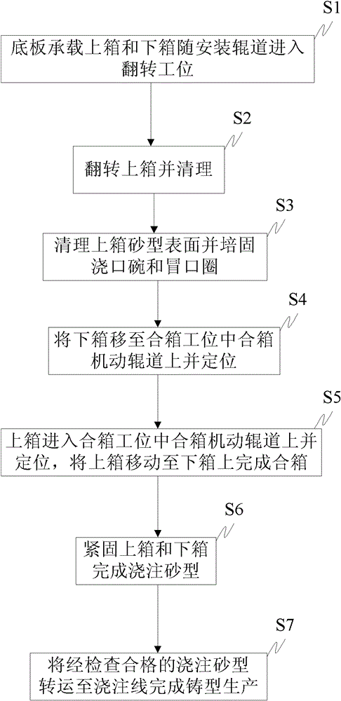
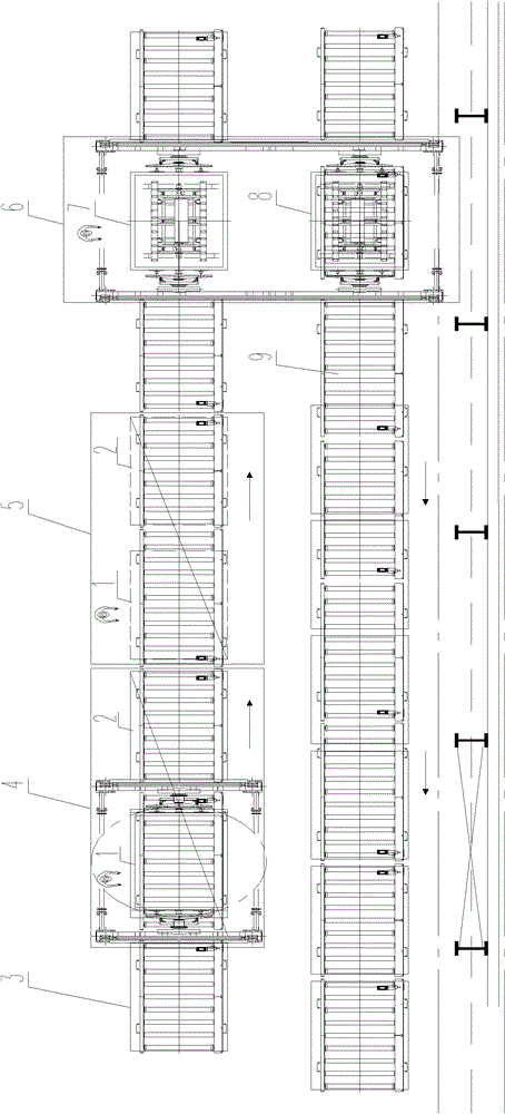
[0022] see figure 1 and image 3 As shown, the box closing method of the present invention specifically comprises the following steps:

[0023] S1: The bottom plate 3 carries the upper box 1 and the lower box 2 and enters the turning station 4 along with the installation roller table. The bottom surface of the upper box 1 and the bottom surface of the lower box 2 are placed on the bottom plate 3. Load the upper box 1 and the lower box 2 into the turning station 4, wherein the parting surface of the upper box 1 and the parting surface of the lower box 2 are placed upward relative to the bottom plate 3; before this step, the manufacture of the lower box 2 has been completed , and the bottom surface of the lower box 2 is placed on the bottom plate 3, and the parting surface of the lower box 2 is upward so that the parting surface of the upper box 1 is fastened on it;

[0024] S2: Turn over the upper box 1 and clean it, turn over the upper box 1 at the turning station 4 and clea...

Embodiment 2

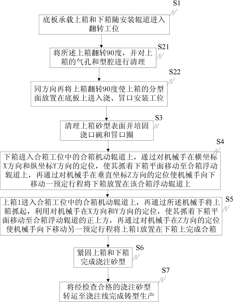
[0031] Such as figure 2 As shown, on the basis of Embodiment 1, the method of this embodiment also includes the following further steps:

[0032] Described step S2 comprises:

[0033] S21: Turn over the upper case 1 by 90 degrees, and clean the air holes and cavity of the upper case 1;

[0034] S22: In the same direction, turn the upper box 1 over 90 degrees so that the parting surface of the upper box 1 is placed on the bottom plate 3 and enter the pouring and riser installation station 5;

[0035] The step S4 is specifically:

[0036] The lower box 2 enters the box closing motorized roller table 7 in the box closing station 6. By positioning the manipulator in the abscissa X direction and the vertical coordinate Y direction, it grasps the lower box 2 and moves to the box closing floating roller table. 8, and then by positioning the manipulator in the vertical coordinate Z direction, the manipulator moves downward for a predetermined stroke to place the lower case 2 on th...


PUM


Abstract

The invention discloses a box assembling method which is applied to the field of casting. The technology comprises the following steps: 1, placing the bottom surfaces of an upper box and a lower box onto a base plate and enabling the upper and lower boxes to enter into a turning station; 2, at the turning station, turning the upper box and cleaning pores and cavity of the upper box, placing a parting surface of the upper box onto the base plate and enabling the upper box to entering into a pouring and riser mounting station; 3, at the pouring and riser mounting station, cleaning a sand-scraping surface of a sand mould of the upper box, and cultivating and fixing a pouring bowl and a riser bush on the sand mould; 4, causing the lower box to enter into a box assembling station, utilizing a mechanical arm to position, grasping the lower box, moving the lower box to a box assembling floating rail and primarily positioning; 5, causing the upper box to enter into the box assembling station, utilizing the mechanical arm to grasp the upper box and move onto the lower box according to a positioning standard of the lower box, thereby finishing the box assembling; and 6, fastening the upper box and the lower box. Before the box assembling, the turning in advance is performed and a pouring port and a riser are cultivated and fixed, so that the problem of secondary pollution to the cavity of the sand mould after the box assembling is effectively solved.

Description

technical field [0001] The invention relates to a casting process, in particular to a box closing method. Background technique [0002] At present, in casting production, there are usually two ways to combine the upper box and the lower box. One method is to use a crane to lift the upper box, and after manually turning over, the sprue bowl, riser ring, etc. are cultivated, and then Use the closing pin to position the closing box; another common closing method is to turn the upper box over by the manipulator and then close the box directly by mechanically assisted positioning, and then cultivate the sprue bowl, riser ring and other accessories for pouring sand molds. part. [0003] Both of the above two commonly used methods of closing boxes have disadvantages to varying degrees. The first method is purely manual, with low production efficiency and great safety hazards; The head (the end of the casting sand core) is scratched, and in serious cases, the core head will be cru...

Claims


Application Information

Patent Timeline
Patent Type & Authority Patents(China)
IPC IPC(8): B22D33/04
Inventor 景丹孙宝君王金朋崔世海贾非修磊魏训谦袁树林
Owner CRRC QIQIHAR ROLLING CO LTD
Learn More