Eureka AIR delivers breakthrough ideas for toughest innovation challenges, trusted by R&D personnel around the world.

Automatic pipe end flattening machine

A technology for flat mouth machines and pipe fittings, applied in the field of flat mouth machines, can solve the problems of uneven technical level, proficiency and work attitude, labor consumption, difficult to control, etc., so as to achieve easy control of processing quality, save processing time, reduce The effect of production costs

Active Publication Date: 2013-04-03
TAIGU COUNTY XINKA NAIFU PLUMBING EQUIP CO LTD +1
View PDF12 Cites 13 Cited by
  • Summary
  • Abstract
  • Description
  • Claims
  • Application Information

AI Technical Summary

Problems solved by technology

[0002] The existing flat mouth machine includes a frame, a power head assembly is installed at one end of the upper part of the frame, and a feeding device for making the lower clamp move horizontally along the bed is installed at the other end of the upper part of the frame. The clamping mechanism of the upper fixture, this kind of flat mouth machine needs multiple stations to complete the port processing of the T-shaped tee or L-shaped two-way or straight cylindrical two-way of the pipe connector. This kind of port flat mouth has the following disadvantages: 1. 1. It takes a lot of labor to process a part, the production cycle is long, the efficiency is low, and the cost is high; 2. Since each port of the processed part has to be repositioned, the technical level, proficiency and working attitude of each operator are uneven , so the product quality is unstable and difficult to control; 3. When processing each port, workers need to put the workpiece on the processing position, and improper operation is prone to safety accidents

Method used


Image

  • Automatic pipe end flattening machine
  • Automatic pipe end flattening machine
  • Automatic pipe end flattening machine

Examples


Embodiment Construction

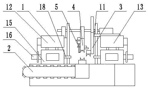
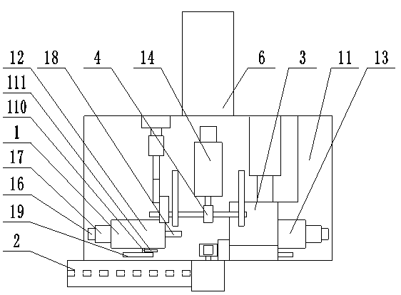
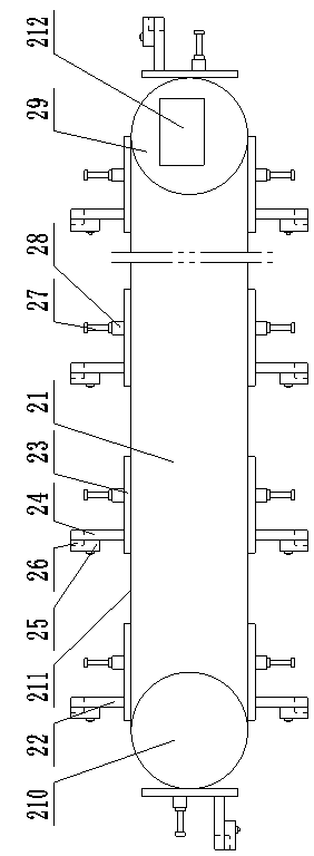
[0033] Such as figure 1 — Figure 9 As shown, the present invention is an automatic flat mouth machine for pipe fittings, comprising a power head assembly 1, a frame 11, an automatic feeding device 2, an automatic material grabbing device 3, an automatic clamping device 4, an automatic unloading device 5 and an automatic receiving device 6. The power head assembly 1 is installed on the frame 11, the frame 11 on one side of the power head assembly 1 is provided with an automatic feeding device 2, and the frame 11 on the other side of the power head assembly 1 is provided with an automatic retracting device. Material device 6, the frame 11 at the feeding end of the automatic feeding device 2 is provided with an automatic grabbing device 3, and the automatic clamping device 4 arranged on the top of the frame 11 fixes the workpiece on the working area of ​​the power head assembly 2.

[0034] The structure of the automatic feeding device 2 is as follows: the automatic feeding mech...


PUM


Abstract

The invention relates to an automatic pipe end flattening machine, which belongs to the technical field of an end flattening machine. The invention provides an automatic pipe end flattening machine capable of machining a workpiece in one step as long as the workpiece is arranged on a feeding device and stable in machining quality. In order to solve the technical problems, the invention adopts the technical scheme as follows: the automatic pipe end flattening machine comprises a power head assembly, a stander, an automatic feeding device, an automatic grabbing device, an automatic clamping device, an automatic unloading device and an automatic collecting device, the power head assembly is installed on the stander, the stander on one side of the power head assembly is provided with the automatic feeding device, the stander on the other side of the power head assembly is provided with the automatic collecting device, the stander on the tail end of the automatic feeding device is provided with the automatic grabbing device, and the automatic clamping device which is arranged on the top of the stander fixes the workpiece into a working area of the power head assembly. The automatic pipe end flattening machine is used for flattening ends of a pipe.

Description

technical field [0001] The invention relates to an automatic flat mouth machine for pipe fittings, which belongs to the technical field of flat mouth machines. Background technique [0002] The existing flat mouth machine includes a frame, a power head assembly is installed at one end of the upper part of the frame, and a feeding device for making the lower clamp move horizontally along the bed is installed at the other end of the upper part of the frame. The clamping mechanism of the upper fixture, this kind of flat mouth machine needs multiple stations to complete the port processing of the T-shaped tee or L-shaped two-way or straight cylindrical two-way of the pipe connector. This kind of port flat mouth has the following disadvantages: 1. 1. It takes a lot of labor to process a part, the production cycle is long, the efficiency is low, and the cost is high; 2. Since each port of the processed part has to be repositioned, the technical level, proficiency and working attit...

Claims


Application Information

Patent Timeline
IPC IPC(8): B23D79/00B23Q7/00B23Q7/04B23Q3/00
Inventor 刘旭昇周永军
Owner TAIGU COUNTY XINKA NAIFU PLUMBING EQUIP CO LTD
Why Eureka
Eureka Blog
Learn More