Intelligent siphoning and water-saving water tank

A water tank and intelligent technology, which is applied to washing equipment with water tanks, water supply devices, buildings, etc., can solve the problems of difficult realization, complex structure of water tanks, and inability to form a stable siphon, and achieve good water-saving performance and good adaptability.

Inactive Publication Date: 2013-04-03
ZHEJIANG TONGJI VOCATIONAL COLLEGE OF SCI & TECH
View PDF7 Cites 7 Cited by
  • Summary
  • Abstract
  • Description
  • Claims
  • Application Information

AI Technical Summary

Problems solved by technology

Now there are also intelligent public toilet flushers developed by some people. After sensing that someone is using it, the mechanical outlet valve is opened directly through the solenoid valve, but the structure of the water tank is complicated and difficult to realize; there is also a fully automatic water-saving water tank. After someone uses it, control the water inlet valve to enter the water, and when the water level exceeds the minimum water level, the inverted U siphon valve opens to realize automatic flushing
However, the general mechanical inverted U-shaped siphon valve has certain requirements on the water inlet speed. When the water inlet speed is slow, a stable siphon cannot be formed, and the water will slowly flow out of the inverted U-shaped pipe.
In addition, the mechanical siphon valve, the flushing water volume is fixed after the siphon is generated, and the flushing water volume cannot be adjusted according to the site conditions

Method used


Image

  • Intelligent siphoning and water-saving water tank

Examples


Embodiment Construction

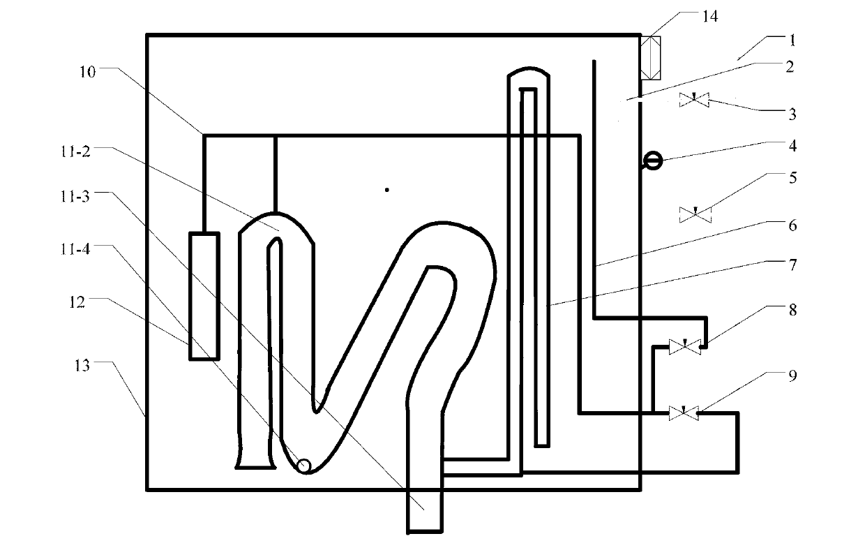
[0011] Attached below figure 1 The present invention is further described.

[0012] An intelligent siphon water-saving water tank, comprising a box body 13, a controller 14, a water inlet 2 and a water outlet 11-3 are arranged on the box body 13, a water level sensor 4 and a siphon valve 11 are arranged inside the box body 13, and a water inlet 2 A water inlet pipe 1 is provided at the place, and a water inlet solenoid valve 3 is installed on the water inlet pipe 1. The water outlet 11-3 is connected to the siphon valve 11. The siphon valve 11 is formed by connecting an inverted U-shaped pipe 11-2 and a? The top of the type tube 11-2 communicates with the water outlet 11-3 through the air thin tube 10, the air thin tube 10 is provided with a siphon control solenoid valve 9, and the controller 14 communicates with the water level sensor 4, the water inlet solenoid valve 3 and the siphon control valve respectively. The solenoid valve 9 is connected by a line. Described ventil...


PUM


Abstract

The invention relates to a water tank and in particular to an intelligent siphoning and water-saving water tank. The intelligent siphoning and water-saving water tank comprises a tank body, wherein the tank body is provided with a controller, a water inlet and a water outlet; the tank body is internally provided with a water level sensor and a siphoning valve; a water inlet pipe which is provided with an inlet water electromagnetic valve is arranged at the water inlet; the water outlet is connected to the siphoning valve; the siphoning valve is formed by connecting a converse U-shaped pipe and a question mark shaped elbow pipe, and a small hole is arranged at the joint of the converse U-shaped pipe and the question mark shaped elbow pipe; the top end of the converse U-shaped pipe is communicated with a water outlet through a ventilated tubule; the ventilated tubule is provided with a siphoning control electromagnetic valve; and the controller is respectively connected to the water level sensor, the inlet water electromagnetic valve and the siphoning control electromagnetic valve through circuits. The intelligent siphoning and water-saving water tank further comprises a pressurizing pipe with the top end per se communicated with the ventilated tubule. The intelligent siphoning and water-saving water tank, disclosed by the invention, has the advantages of realizing stable formation of siphoning, being good in adaptability as well as water saving performance, and solving the disadvantages that a mechanical siphoning valve cannot keep the water level and does not adapt to small flow of inlet water.

Description

technical field [0001] The invention relates to a water tank, in particular to an intelligent siphon water-saving water tank. Background technique [0002] At present, most of the water tanks used in public toilets use mechanical manual control flushing methods, and the flushing is controlled by manual pulling wires, which is difficult to meet hygienic requirements. There is also a timing flushing device, the water tank is continuously fed, and when a certain amount of water is reached, the water is automatically flushed down. This mode also flushes water when no one uses it, and the waste is serious. There is also an inductive flushing device whose working principle is to detect whether someone uses the toilet through a photoelectric method, so as to control the water intake of the electromagnetic valve and realize water saving. Now there are also intelligent public toilet flushers developed by some people. After sensing that someone is using it, the mechanical outlet valv...

Claims


Application Information

Patent Timeline
IPC IPC(8): E03D1/00E03D1/12E03D1/30
Inventor 景秀眉
Owner ZHEJIANG TONGJI VOCATIONAL COLLEGE OF SCI & TECH
Why Eureka
Try Eureka