Supercharge Your Innovation With Domain-Expert AI Agents!

Cruciform member module

A cross-shaped component technology, which is applied in the field of cross-shaped component modules, can solve problems such as unsuitable cross connections and no blocks provided, and achieve the effects of ensuring wall section size, sufficient blending, and fast construction progress

Inactive Publication Date: 2013-04-03
HARBIN HONGSHENG REAL ESTATE DEV GRP CO LTD
View PDF5 Cites 4 Cited by
  • Summary
  • Abstract
  • Description
  • Claims
  • Application Information

AI Technical Summary

Problems solved by technology

The T-shaped component module is used at the connection part of two vertically arranged walls in the house, and is not suitable for the cross connection of two vertically intersecting walls in the house, and there is no provision in the prior art for connecting two vertical walls in the house cross wall blocks

Method used


Image

  • Cruciform member module
  • Cruciform member module
  • Cruciform member module

Examples


specific Embodiment approach 1

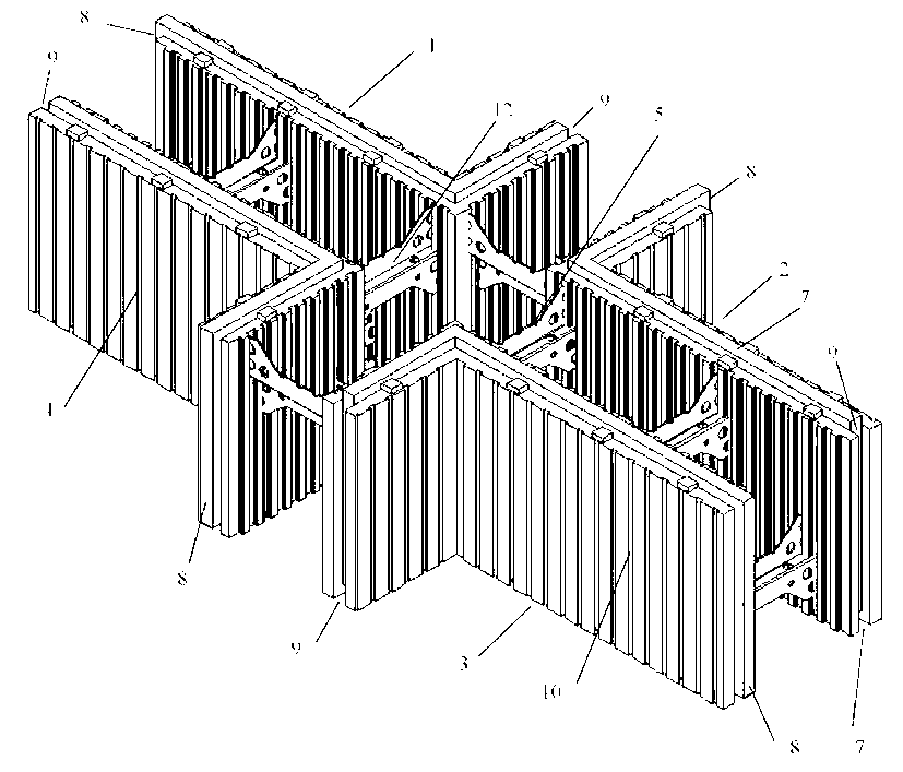
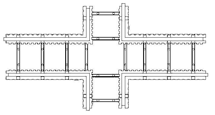
[0010] Specific implementation mode one: as Figure 1-7 As shown, a cross-shaped component module described in this embodiment is composed of four module corner plates 1, 2, 3, 4 and a plurality of core ribs 12; the four module corner plates 1, 2, 3, 4 (right angle board) is made of thermal insulation material; the four module corner plates 1, 2, 3, 4 are arranged in a cross shape, and a plurality of misplaced core ribs are set in the cross-shaped inner cavity formed by the four module corner plates. Two adjacent module angle plates are connected by core ribs 12, and a plurality of core ribs form vertical and horizontal flower holes; the plurality of core ribs 12 are connecting members having the same function as steel bars.

specific Embodiment approach 2

[0011] Specific implementation mode two: as Figure 1-9 As shown, the core rib 12 in this embodiment is composed of two core rib side plates 12-1 and a core rib main board 12-2, and the core rib main board 12-2 is composed of two sub-boards 12-2 with the same length. 2-1 and transition plate 12-2-2, the two sub-plates 12-2-1 are arranged in a staggered butt joint, and the two are connected through the transition plate 12-2-2 to form a stepped shape, and the core rib main plate 12-2 The stepped end surfaces at both ends are respectively connected with a core rib plate 12-1. The main plate of the core rib is stepped (with roundabout part: transition plate 12-2-2). The core rib of this structure has strong resistance to deformation and bending, which greatly improves the load-bearing capacity of the wall. When the four module corner plates 1, 2, 3, 4 and the plurality of core ribs 12 are integrally formed in the present invention, the core rib main board 12-2 is inlaid or fixed ...

specific Embodiment approach 3

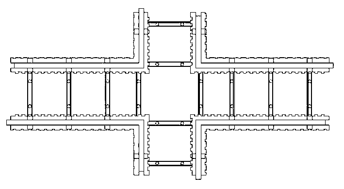
[0012] Specific implementation mode three: as Figure 1-9 As shown, in this embodiment, the outer side of one sub-board 12-2-1 of the two core rib side boards 12-1 is connected with a reinforcing bar position groove 5. Other components and connections are the same as those in the second embodiment. Rib plates 12-3 may also be provided between the stepped end surfaces at both ends of the core rib main plate 12-2 in this embodiment and the core rib side plate 12-1.


PUM


Abstract

The invention relates to a building member and aims at providing a cruciform member module with good bearing performance and good energy-saving and thermal insulation effects to realize intersected penetration cruciform connection of two perpendicular walls in a house. The cruciform member module comprises four module angle plates and a plurality of core ribs, wherein the module angle plates are made of thermal insulation materials and arranged in a cruciform way; the core ribs arranged in a staggered way are arranged in a cruciform inner cavity formed by the four module angle plates; every two adjacent module angle plates are connected through the core ribs; and the core ribs form perpendicular and horizontal pattern holes and are connecting aggregates with the same function as steel bars. The cruciform member module ensures the surface dimensions of the walls, and has the advantages of convenience in mounting, fast construction progress and low cost.

Description

[0001] technical field [0002] The invention relates to a building component, in particular to a cross-shaped component module with energy-saving and heat-preserving effects, which is suitable for house wall construction. Background technique [0003] In order to improve the energy-saving and thermal insulation effect of buildings, prolong the service life of building components, and improve the construction efficiency of buildings, the applicant has developed a variety of building materials made of EPS, including interior walls, exterior walls, floors, roofs, etc. Panel composite modules at different locations of the building. For example, the invention patent application with the publication number CN102162284A and the publication date of August 24, 2011 proposes a T-shaped component module. The T-shaped component module not only has energy-saving and heat-insulating properties, but also has certain load-bearing properties. The T-shaped component module is used at the co...

Claims


Application Information

Patent Timeline
IPC IPC(8): E04C1/00
Inventor 林国海翟洪远林宣佐
Owner HARBIN HONGSHENG REAL ESTATE DEV GRP CO LTD
Features
  • R&D
  • Intellectual Property
  • Life Sciences
  • Materials
  • Tech Scout
  • Unparalleled Data Quality
  • Higher Quality Content
  • 60% Fewer Hallucinations
Learn More