Variable frequency drive shield thrust hydraulic system

A hydraulic system and variable frequency drive technology, applied in fluid pressure actuating devices, mining equipment, servo motors, etc., can solve the problems of low energy efficiency and large coupling between partitions, achieve high energy efficiency, good energy saving effect, and solve the problem of flow coupling Effect

Inactive Publication Date: 2013-04-03
ZHEJIANG UNIV
View PDF10 Cites 0 Cited by
  • Summary
  • Abstract
  • Description
  • Claims
  • Application Information

AI Technical Summary

Problems solved by technology

[0003] In order to overcome the deficiencies of the existing shield propulsion hydraulic system, such as low energy efficiency and large coupling between propulsion zones, the present invention provides a shield propulsion hydraulic system driven by frequency conversion. Adopt the method of using different quantitative pumps to supply oil to different propulsion zones to realize no coupling between propulsion zones

Method used


Image

  • Variable frequency drive shield thrust hydraulic system

Examples


Embodiment Construction

[0011] The present invention will be further described below in conjunction with the accompanying drawings and embodiments.

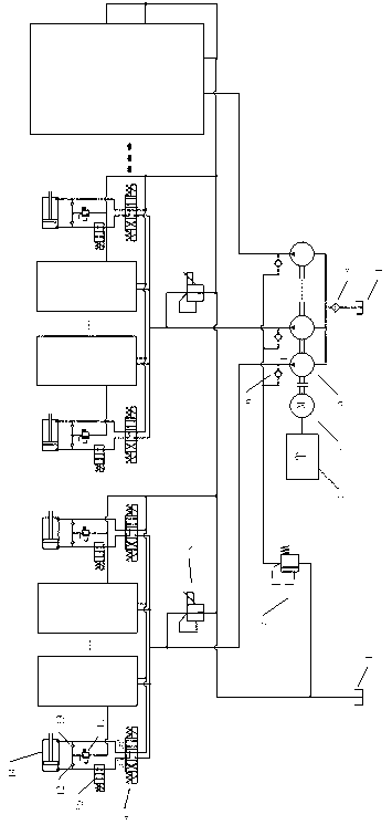
[0012] The present invention comprises oil tank 1, filter 2, frequency converter 3, frequency conversion motor 4, n quantitative pumps 5, n one-way valves 6, safety valve 7, n propulsion partitions with the same structure; the input end of frequency conversion motor 4 and The inverter 3 is connected, the output end of the variable frequency motor 4 is cascaded with n quantitative pumps 5, the oil inlets of n quantitative pumps 5 are connected to the oil tank 1 through filter 2, and the oil outlets of n quantitative pumps 5 are divided into two ways , one way is connected with the oil inlet of the respective one-way valve 6, and the other is connected with the respective propulsion partitions with the same structure, and the oil outlets of the n oil supply check valves 6 are connected to the oil inlet of the safety valve 7, The oil outlet of the safety v...


PUM


Abstract

The invention discloses a variable frequency drive shield thrust hydraulic system, which comprises a fuel tank, a filter, a frequency converter, a variable frequency motor, n dosing pumps, n one-way valves, a safety valve and n thrush sub-areas with the same structure, wherein fuel is supplied to each sub-area independently by the respective dosing pump, and all the dosing pumps for supplying fuel are coaxially connected together and are driven by the same variable frequency motor. Each thrust sub-area comprises a proportional relief valve and i same thrust cylinder hydraulic system branches, and the hydraulic system branch comprises a three-position four-way solenoid directional valve, a two-position two-way solenoid directional valve, a safety valve, two execution one-way valves and a thrust cylinder. In work, the rotational speed of the variable frequency motor is adjusted to control the thrust speed of a shield, so that the loss of valve control of a speed regulator valve is avoided, and the variable rotational speed control has better energy-saving effects than the variable displacement control; and different thrust sub-areas adopt different dosing pumps to supply fuel, so that the flow coupling problem caused by different sub-areas commonly using the same fuel source can be solved.

Description

technical field [0001] The invention relates to a shield propulsion hydraulic system, in particular to an energy-saving shield tunnel propulsion hydraulic system based on variable frequency drive cascaded quantitative pumps. Background technique [0002] The shield propulsion hydraulic system is one of the key subsystems of the shield tunneling equipment. It undertakes the jacking task of the shield machine. Set track. The existing shield propulsion system can be divided into variable pump + speed control valve + overflow valve mode and variable pump + pressure reducing valve mode according to the control mode of the propulsion cylinder. Both of these modes realize the propulsion of the shield by controlling the propulsion pressure and correction tasks. However, the variable variable pump + speed control valve + relief valve mode has the characteristics of oil source overflow loss, the variable variable pump + pressure reducing valve mode has the characteristics of large f...

Claims


Application Information

Patent Timeline
IPC IPC(8): E21D9/093F15B11/16
Inventor 龚国芳杨旭杨华勇王林涛
Owner ZHEJIANG UNIV
Why Eureka
Try Eureka