Drainage control system of water well

A control system and water well technology, applied in waterway system, sewer system, sewage well, etc., can solve problems such as failure of float device, short circuit and leakage, poor safety and reliability, etc., to improve sensitivity and reliability effects of shock and volatility mitigation, shock and volatility avoidance

Active Publication Date: 2015-06-10
ENVIROSYST BEIJING ENVIRONMENTAL ENG & TECH CO LTD
View PDF5 Cites 0 Cited by
  • Summary
  • Abstract
  • Description
  • Claims
  • Application Information

AI Technical Summary

Problems solved by technology

[0002] The drainage of the water well is usually determined according to the water level in the well. When the water level rises to a certain level, the drainage device is turned on for drainage. The existing water well drainage control system usually uses an electric water level sensor to collect the water level signal of the well. , or use a float device to control the opening and closing of the valve, but due to the environmental conditions of the water well, when using an electric water level sensor, more lines will be involved, which is prone to short circuit and leakage problems, and the safety and reliability are relatively low. Poor, and the floating ball device will fail due to scaling and other reasons, therefore, it is necessary to develop a safe and reliable drainage control system suitable for the environment of ponding wells

Method used


Image

  • Drainage control system of water well
  • Drainage control system of water well

Examples


Embodiment Construction

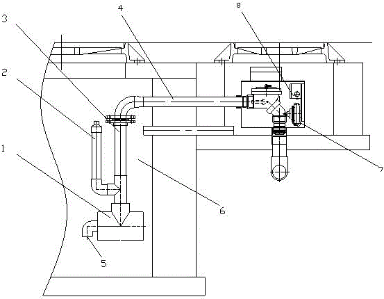
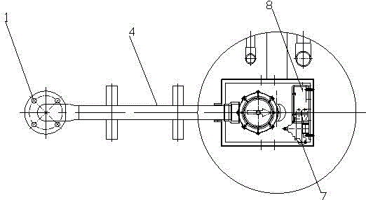
[0017] Such as figure 1 and figure 2 As shown, the present invention provides a water accumulation well drainage control system, and the water accumulation well drainage control system is located in the water accumulation well 6 . The system includes a collector 1 and a drain pipe connected to the collector, and also includes an induction pipe 2 and an induction valve 7 for converting the pressure signal into an electric water level signal. The induction pipe is a standpipe, and its lower end communicates with the collector. The upper end is provided with a pressure signal sampling nozzle for collecting pressure signals, and the pressure signal sampling nozzle is connected with the signal input nozzle of the sensing valve through a pressure tube.

[0018] The system is also provided with a controller 8 for receiving the electric water level signal of the sensing valve, and the electric water level signal output end of the sensing valve is connected with the electric water le...


PUM


Abstract

The invention relates to a drainage control system of a water well, which comprises a collector and a drain pipe which is connected with the collector, also comprises an induction tube and an induction valve which is used for converting a pressure signal into an electric water level signal. The induction tube is a vertical tube, the lower end of the induction tube is communicated with the collector, and the upper end is provided with a pressure signal sampling pipe mouth which is used for acquiring the pressure signal; and the pressure signal sampling pipe mouth is connected with a signal input mouth of the induction valve through a pressure pipe. The drainage control system of the water well is applied to the field of drainage control; the current drainage control device has the defects of low safety, low reliability and poorer water level control due to long time use, caused by the self-design problem, on account of the defects of the current drainage control device, the invention develops the drainage control system which has the advantages of a simple structure, sensitivity in high level control, convenience in installation, low requirement on the environment, reliability in operation, and less maintenance workload, basically can meet the requirement of no maintenance, and adapts to all kinds of water wells (collector wells) and similar situations.

Description

technical field [0001] The invention relates to a drainage control system, which belongs to the field of automatic suction water control. Background technique [0002] The drainage of the water well is usually determined according to the water level in the well. When the water level rises to a certain level, the drainage device is turned on for drainage. The existing water well drainage control system usually uses an electric water level sensor to collect the water level signal of the well. , or use a float device to control the opening and closing of the valve, but due to the environmental conditions of the water well, when using an electric water level sensor, more lines will be involved, which is prone to short circuit and leakage problems, and the safety and reliability are relatively low. Poor, and the floating ball device will fail due to fouling and other reasons. Therefore, it is necessary to develop a safe and reliable drainage control system suitable for the water ...

Claims


Application Information

Patent Timeline
Patent Type & Authority Patents(China)
IPC IPC(8): F16K31/02E03F5/10E03F11/00E03F3/02
Inventor 张健高世宝
Owner ENVIROSYST BEIJING ENVIRONMENTAL ENG & TECH CO LTD
Why Eureka
Try Eureka