LED (Light Emitting Diode) light emitting module and manufacturing method thereof

A light-emitting module and LED chip technology, which is applied to semiconductor devices of light-emitting elements, light sources, electric light sources, etc., can solve the problems that it is difficult to meet the heat dissipation requirements of high-power LED lighting devices, and the thermal resistance of lighting devices is large.

Inactive Publication Date: 2013-04-03
OSRAM GMBH
View PDF5 Cites 2 Cited by
  • Summary
  • Abstract
  • Description
  • Claims
  • Application Information

AI Technical Summary

Problems solved by technology

However, the disadvantage still exists is that since the reflector layer is only mechanically installed on the printed circuit board, the thermal re

Method used


Image

  • LED (Light Emitting Diode) light emitting module and manufacturing method thereof
  • LED (Light Emitting Diode) light emitting module and manufacturing method thereof
  • LED (Light Emitting Diode) light emitting module and manufacturing method thereof

Examples


Embodiment Construction

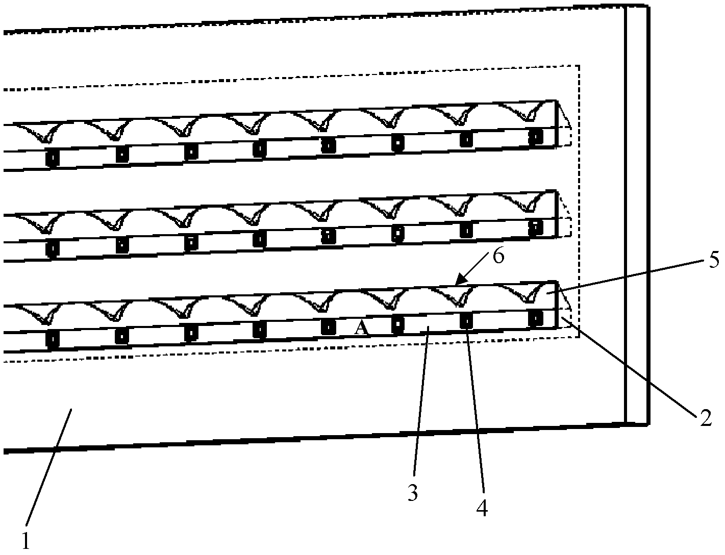
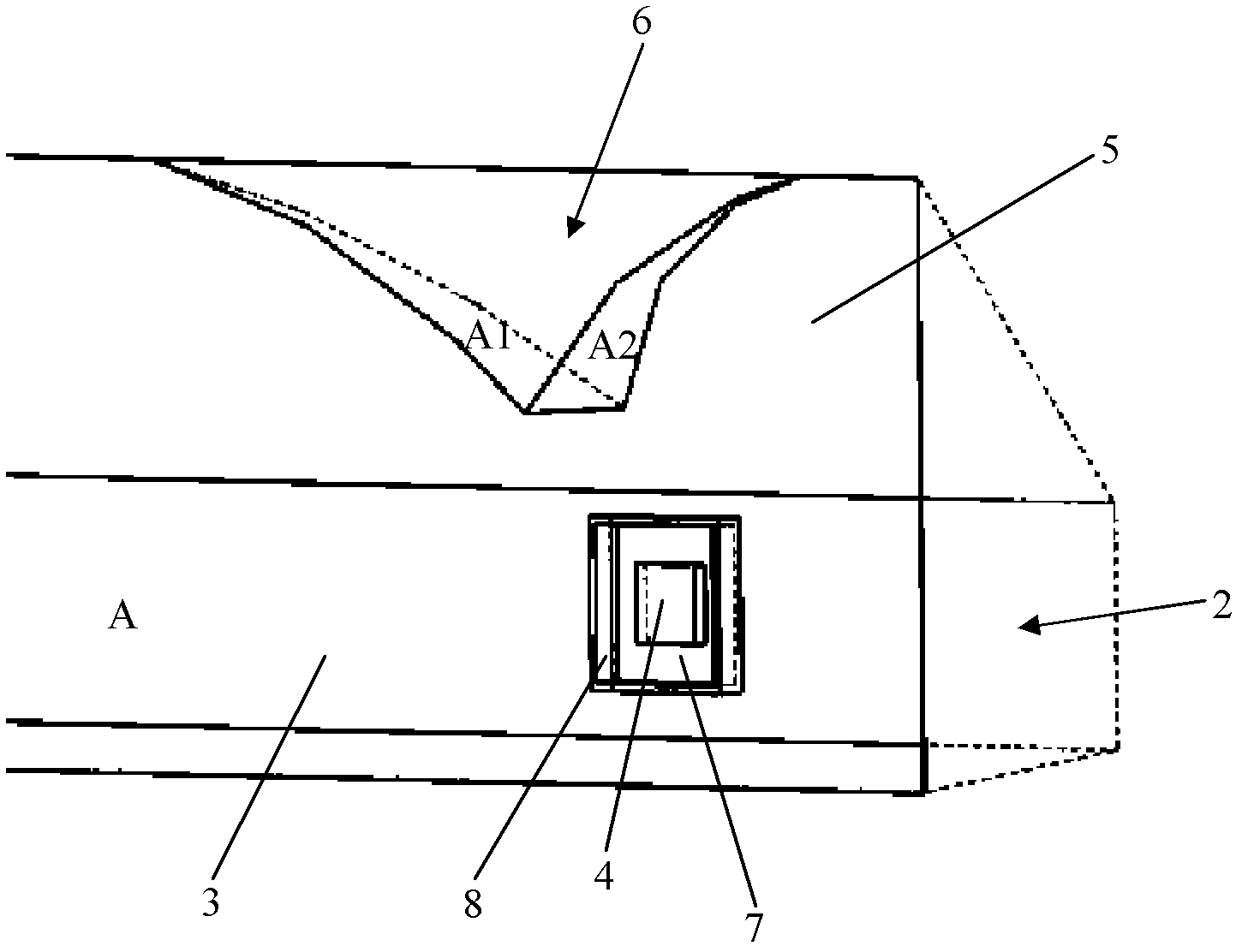
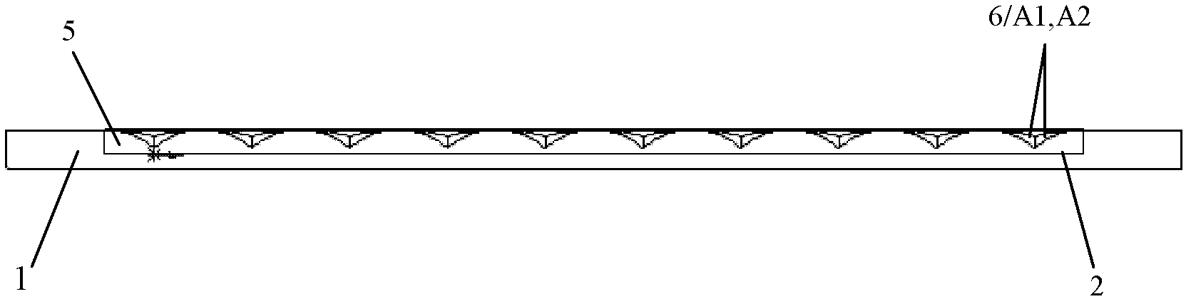
[0031] figure 1 A three-dimensional view of the LED light-emitting module according to the present invention is shown in, wherein the LED light-emitting module has a bottom plate 1, a reflector 5, a printed circuit board 3 and an LED chip 4. In this preferred embodiment, in order to save manufacturing costs and reduce assembly steps, the base plate 1 is subjected to a processing process such as hot die casting or stamping, so that the reflector 5 is integrally formed on the base plate 1. After this treatment process, at least one groove 2 (three in this embodiment) is formed in the bottom plate 1 at the same time, and the groove 2 has a flat bottom and side walls. The bottom may be processed by milling, for example, to form a mounting surface A for mounting the printed circuit board 3, wherein the LED chip 4 is mounted on the printed circuit board 3 in particular by using the COB process. The sidewall of the groove 2 itself serves as the reflector 5, thereby further avoiding li...


PUM


Abstract

The invention relates to an LED (Light Emitting Diode) light emitting module, which is provided with a bottom plate (1) with at least one groove (2) and at least one printed circuit board (3) with an LED chip (4) array, wherein the at least one printed circuit board (3) is arranged in the groove (2) respectively; the LED light emitting module is characterized in that each LED chip (4) is directly arranged on the printed circuit board (3) by using a COB (Chip On Board) process; and a reflector (5) which is positioned on a side wall of the groove (2) is also arranged to reflect light from the LED chip (4). In addition, the invention also relates to a manufacturing method of the LED light emitting module. According to the LED light emitting module, a polarization effect can be produced, so that the LED light emitting module is particularly suitable for roadway lighting; and the LED light emitting module also has the advantages of simple structure, low cost and small heat resistance.

Description

Technical field [0001] The invention relates to an LED light-emitting module and a manufacturing method thereof. Background technique [0002] With the development of LED technology, many types of LED lighting devices can replace conventional halogen lamps and are widely used in the field of road lighting. In the prior art, an LED lighting device that can provide 1w or 3w high power is known. This kind of lighting device consists of a plurality of individually packaged LED chips to form a matrix module, due to the existence of too many thermal interfaces (such as chip to lead frame, lead frame to solder paste, solder paste to printed circuit board, printed circuit board to heat sink ) Resulting in higher thermal resistance of this lighting device. And since the light source of this kind of lighting device is a symmetrically distributed point light source, it can only provide a circular light distribution, which is disadvantageous for road lighting. In another known embodiment,...

Claims


Application Information

Patent Timeline
IPC IPC(8): F21S2/00F21V7/22F21V19/00F21Y101/02
CPCF21K9/00H01L25/0753H01L33/60F21K9/90F21W2131/103H01L2924/0002F21Y2115/10H01L2924/00
Inventor 钟传鹏明玉生陈鹏刘廷明
Owner OSRAM GMBH
Why Eureka
Try Eureka