Green wave coordination control method for artery facing to running speed section

A driving speed and coordinated control technology, which is applied to the traffic control system, traffic control system, instruments and other directions of road vehicles. Lack of comparative analysis of the operation effect of the coordinated control scheme, etc.

Active Publication Date: 2013-04-03
SOUTH CHINA UNIV OF TECH
View PDF2 Cites 33 Cited by
  • Summary
  • Abstract
  • Description
  • Claims
  • Application Information

AI Technical Summary

Problems solved by technology
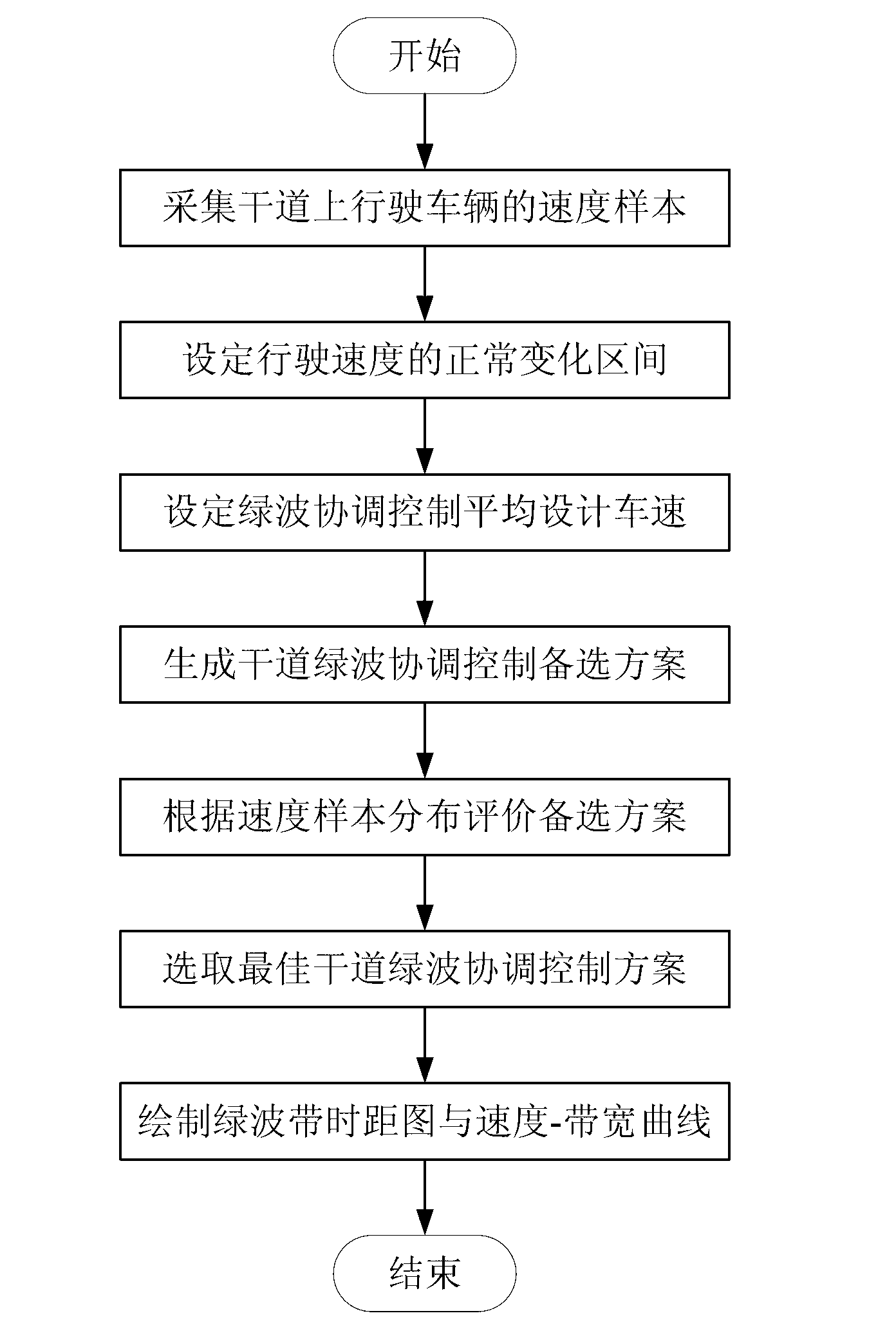
[0004] (1) The existing control methods either use a certain fixed speed value as the basis for the optimization of the green wave coordinated control scheme, or obtain an optimal green wave driving speed value in the final design, without considering the range of vehicle speed changes sex
[0005] (2) The existing control method does not take into account the uncertainty of the vehicle speed and the discreteness of the team's driving, and does not consider the change characteristics and distribution of the speed of the main road in different driving directions
[0006] (3) The existing control methods cannot comprehensively analyze and evaluate the green wave coordinated control

Method used


Image

  • Green wave coordination control method for artery facing to running speed section
  • Green wave coordination control method for artery facing to running speed section
  • Green wave coordination control method for artery facing to running speed section

Examples


Embodiment 1

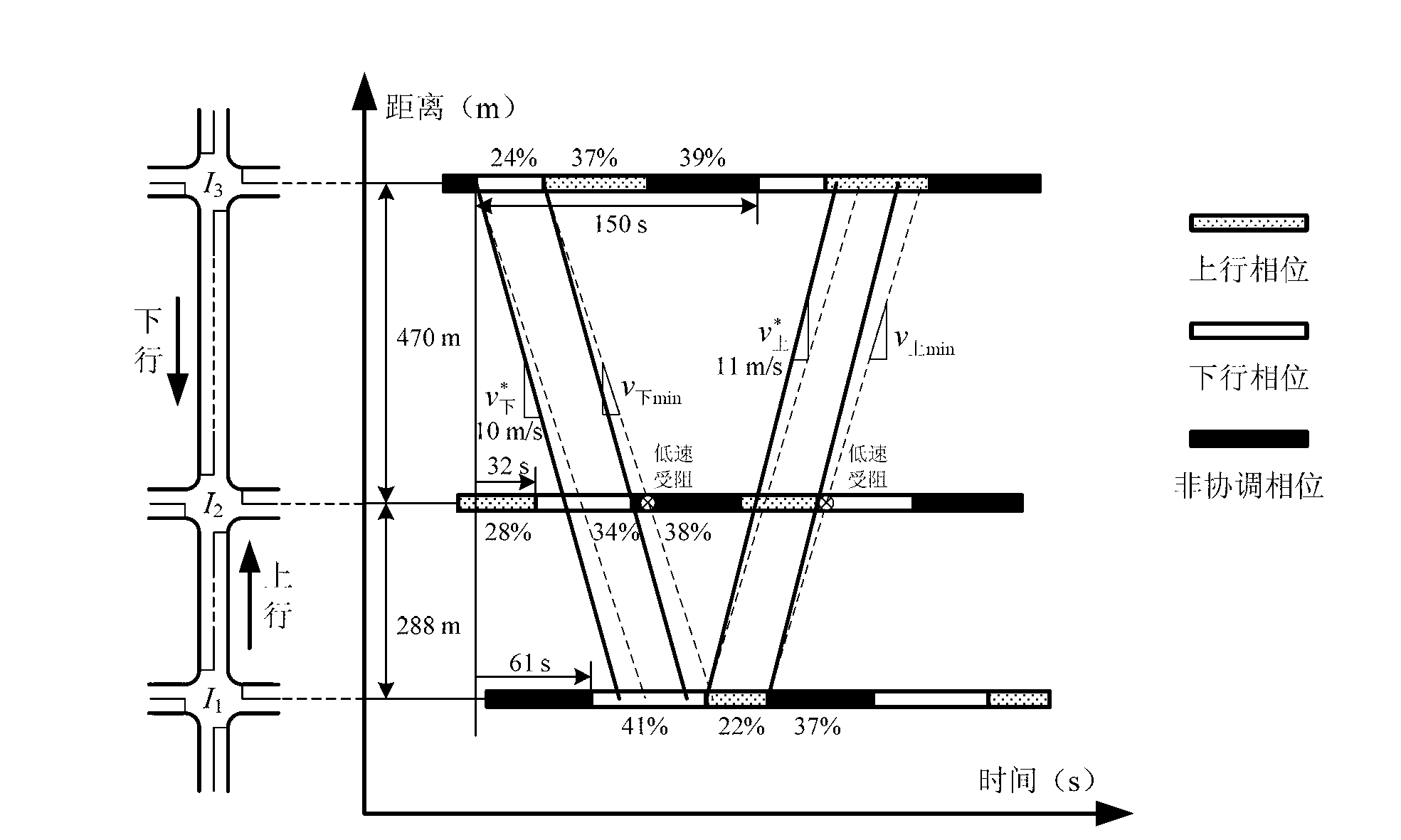
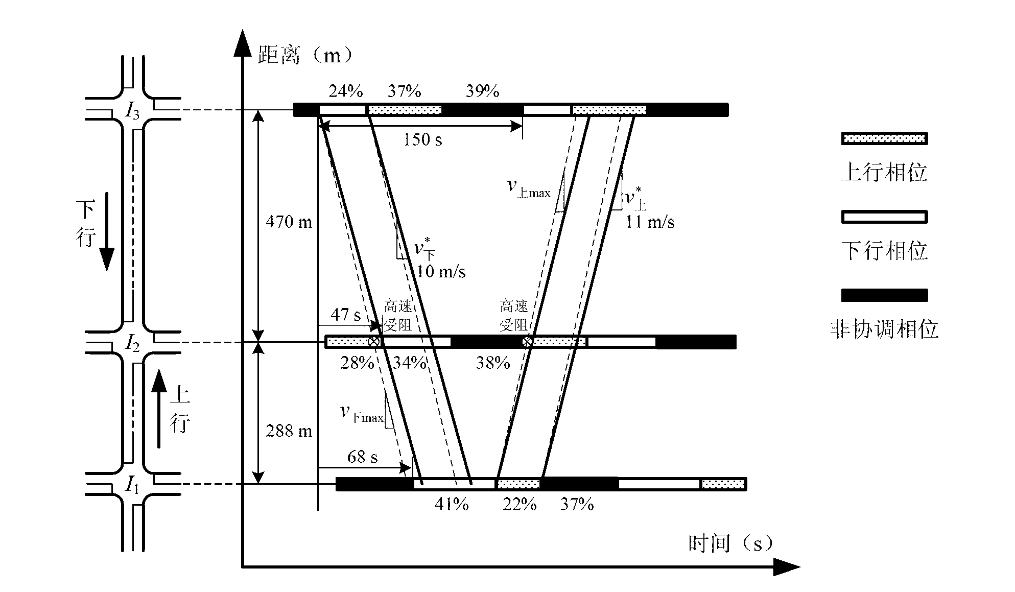
[0046] It is known that there are 3 signalized intersections I on a certain arterial road 1 , I 2 , I 3 , defined from the intersection I 1 to intersection I 3 The direction of is the uplink direction of the arterial road, from the intersection I 3 to intersection I 1 The direction is the downlink direction of the arterial road, and the adjacent intersection I 1 with I 2 , I 2 with I 3 The distances between them are 288m and 470m respectively. Each intersection adopts a three-phase control method, and the uplink and downlink directions adopt the separate release phase of the entrance. The signal timing design parameters are shown in Table 1 (for the convenience of calculation and drawing, it is assumed that the green light time of each phase is equal to the phase time, That is, the sum of the green-to-signal ratios of each intersection phase is 1, and the green light interval is 0s).

[0047] Assume that the collection of uplink speed samples collected by the speed m...

Embodiment 2

[0072] This embodiment is the same as Embodiment 1 except for the following:

[0073] Step 3: Evaluate the alternatives according to the distribution of driving speed samples (numerical calculation method);

[0074] According to the probability distribution (uniform distribution) of the uplink and downlink speed samples and the uplink and downlink green wave bandwidth values ​​obtained under the three phase difference schemes (as shown in Table 3 and Table 4), each phase can be calculated separately The mathematical expectation of the sum of the two-way green wave bandwidths of the difference scheme. For phase difference scheme 1, the expected bandwidth of the uplink green wave Downlink green wave bandwidth expectation The mathematical expectation E(B) of the sum of the two-way green wave bandwidth| S1 =E(B 上 )+E(B 下 )=0.392; For the phase difference scheme 2, the expected bandwidth of the uplink green wave Downlink green wave bandwidth expectation The mathematical ...


PUM


Abstract

The invention discloses a green wave coordination control method for an artery facing to a running speed section. The green wave coordination control method comprises the following steps of: collecting speed samples of vehicles running on the artery; setting a normal variable section of the running speed; setting a mean design vehicle speed in a green wave coordination control manner; generating green wave coordination control alternative offers of the artery; evaluating the alternative offers according to distribution of the running speed samples; selecting an optimal green wave coordination control alternative offer of the artery; and drawing a green wave band time-distance graph and a running speed-green wave band width curve. The green wave coordination control method for the artery provided by the invention can meet the green wave coordination control requirements of a motorcade within a certain running speed section to the greatest extent, so that the vehicles of the motorcade in the running speed section can be located within green wave band width of the artery as far as possible; and the adaptability, robustness and the like of the green wave coordination control alternative offer of the artery can be improved.

Description

technical field [0001] The invention relates to traffic signal coordinated control technology, in particular to a green wave coordinated control method for arterial roads oriented to driving speed intervals. Background technique [0002] Due to the limited level of urban traffic control in my country, the lack of road traffic management facilities, the overall traffic quality of traffic participants is not high, and the interference between various traffic flows is serious, the urban traffic signal control system has a high degree of complexity and uncertainty. How to reasonably set up a signal timing scheme with certain adaptability for a traffic period? How to scientifically preset a limited number of optional signal timing schemes for a control system? How to ensure that a good control effect can still be obtained when the characteristic parameters of the traffic system are disturbed and changed? It is an important practical problem faced by urban traffic signal control...

Claims


Application Information

Patent Timeline
IPC IPC(8): G08G1/081
Inventor 卢凯杨兴徐建闽
Owner SOUTH CHINA UNIV OF TECH
Why Eureka
Try Eureka