Support structure for boss

A technology of supporting structures and bosses, applied in the installation of cables, busbars, bases/shells, etc., can solve problems such as cracks, electrical connection failures, failures, etc., to improve dimensional accuracy, prevent short shots, and prevent cracks Effect

Active Publication Date: 2013-04-03
YAZAKI CORP
View PDF5 Cites 2 Cited by
  • Summary
  • Abstract
  • Description
  • Claims
  • Application Information

AI Technical Summary

Problems solved by technology

Therefore, this may cause defects such as electrical connection failure or malfunction
In addition, when the part 19 is assembled, the load of the part 19 is applied to the boss 17 from a direction inclined with respect to its axis, and the stress concentrates on the corner portion where the outer peripheral surface of the boss 17 intersects the upper surface of the reinforcing rib 21. , making cracks possible

Method used


Image

  • Support structure for boss
  • Support structure for boss
  • Support structure for boss

Examples


Embodiment Construction

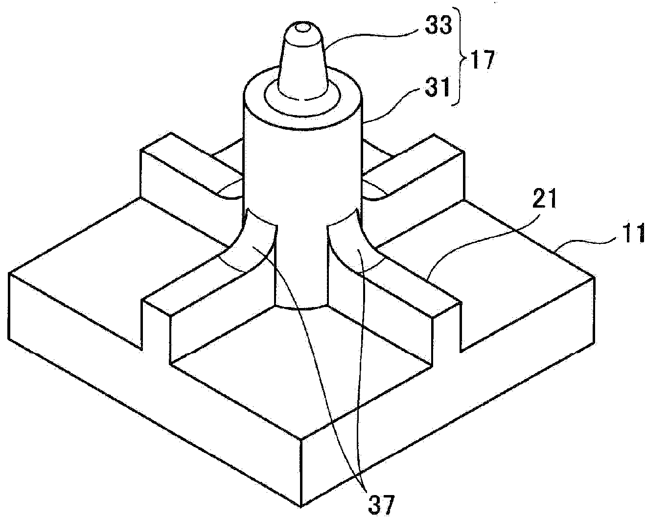
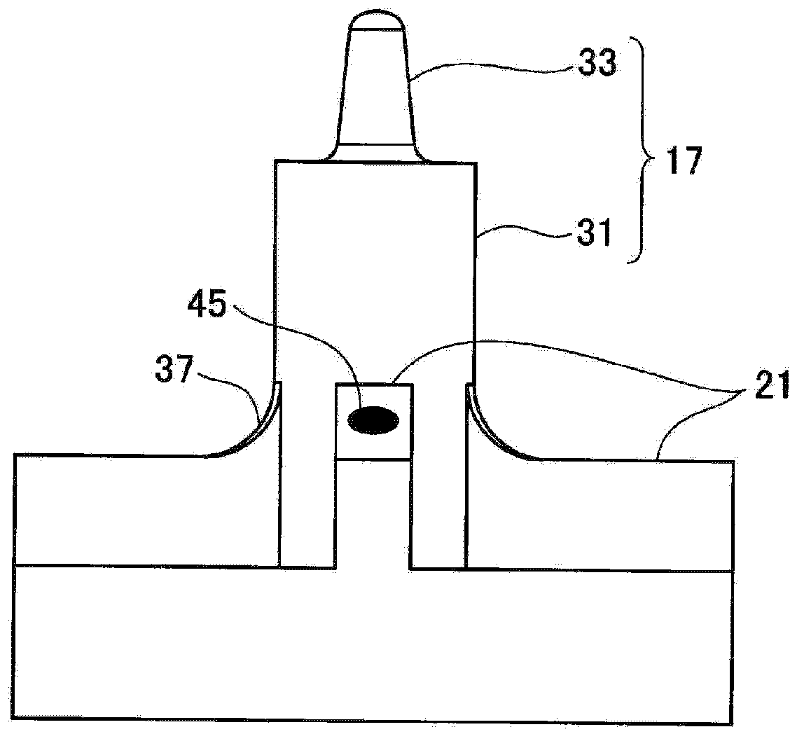
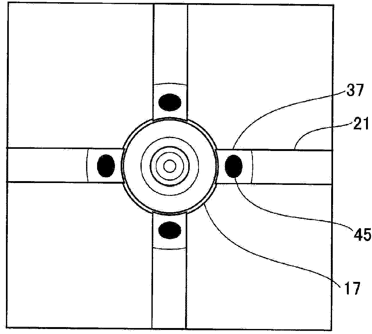
[0026] Hereinafter, a support structure for a boss of a resin molded product according to an embodiment of the present invention will now be described with reference to the accompanying drawings. In this example, the description will be formed in Figure 8 with Figure 9 The support structure for the boss 17 in the electrical junction box shown in . Also, in the following descriptions, configurations other than the support structure for bosses are made with Figure 8 with Figure 9 are denoted by the same reference numerals as those in , and a detailed description thereof will be omitted.

[0027] First, in order to easily understand the support structure for the boss 17 according to the present invention, the support structure for the boss 17 according to the prior art will be described.

[0028] The base plate 11 forming the bottom surface of the frame body 13 is provided with a plurality of bosses 17 ( Figure 8 ). The boss 17 includes a body portion 31 formed in a cylin...


PUM


Abstract

There is provided a support structure for a boss of a resin molded product. A plurality of cylindrical bosses stands up from one surface of a base plate to support a component. A plurality of reinforcing ribs extends radially from an outer circumferential surface of at least one of the bosses. The reinforcing ribs are arranged so as to be spaced apart from each other at a regular interval in a circumferential direction of the at least one of the bosses. Building-up portions are formed only on corner portions in which the outer circumferential surface of the at least one of the bosses and the reinforcing ribs intersect with each other.

Description

[0001] The entire disclosure of Japanese Patent Application No. 2011-210580 filed on September 27, 2011 including specification, drawings and claims is incorporated herein by reference. technical field [0002] The present invention relates to a support structure for a boss of a resin molded product. Background technique [0003] As an assembly member made of resin, there is known an insert-mold type electrical junction box in which bus bars for conductive paths are insert-molded to form a desired circuit pattern. Such as Figure 8 As shown in , the electrical junction box includes: a base plate 11 into which a bus bar is inserted; a frame body 13 erected upward from one side of the base plate 11 and spaced apart from each other; and a connector housing 15 (for example, see Patent Document 1 ). The frame body 13 is attached to a case or the like to be assembled, and the connector housing 15 is configured to house external connection terminals of circuits in the frame body 1...

Claims


Application Information

Patent Timeline
Patent Type & Authority Applications(China)
IPC IPC(8): H01R13/46H02G3/16
CPCH02G3/081H02G3/16H02G3/08H02G5/00
Inventor 古贺健郎清水勇勋
Owner YAZAKI CORP
Why Eureka
Try Eureka