Document transporter

A conveyor and document technology, applied in the directions of transportation and packaging, object supply, positioning objects, etc., can solve the problems of inability to reduce manufacturing costs, unfavorable assembly components, etc., and achieve the effect of structure simplification

Inactive Publication Date: 2013-04-03
JAPAN CASH MASCH CO LTD
View PDF8 Cites 4 Cited by
  • Summary
  • Abstract
  • Description
  • Claims
  • Application Information

AI Technical Summary

Problems solved by technology

The device shown in Patent Document 4 disadvantageously has a greater number of assembly elements and cannot reduce manufacturing costs because it

Method used


Image

  • Document transporter
  • Document transporter
  • Document transporter

Examples


Embodiment Construction

[0034] The following will combine these drawings Figures 1 to 16 An embodiment of the document feeder according to the present invention will be described. The word "document" as used herein means a note, banknote, coupon, bond, tender, currency equivalent or any paper of value.

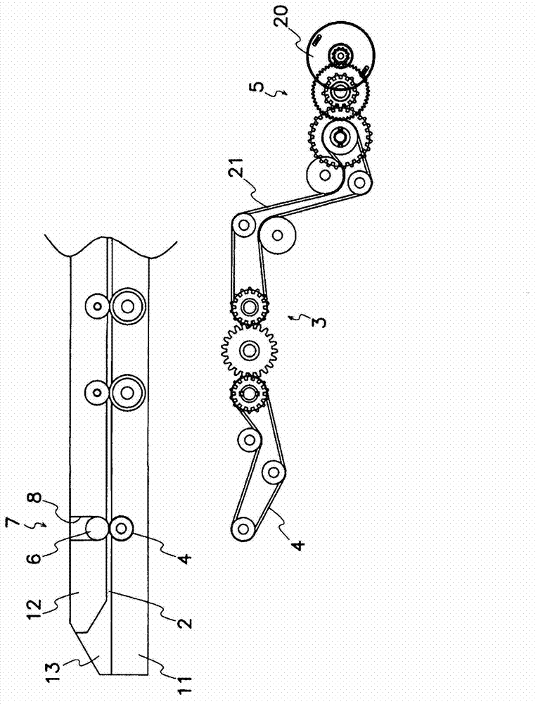
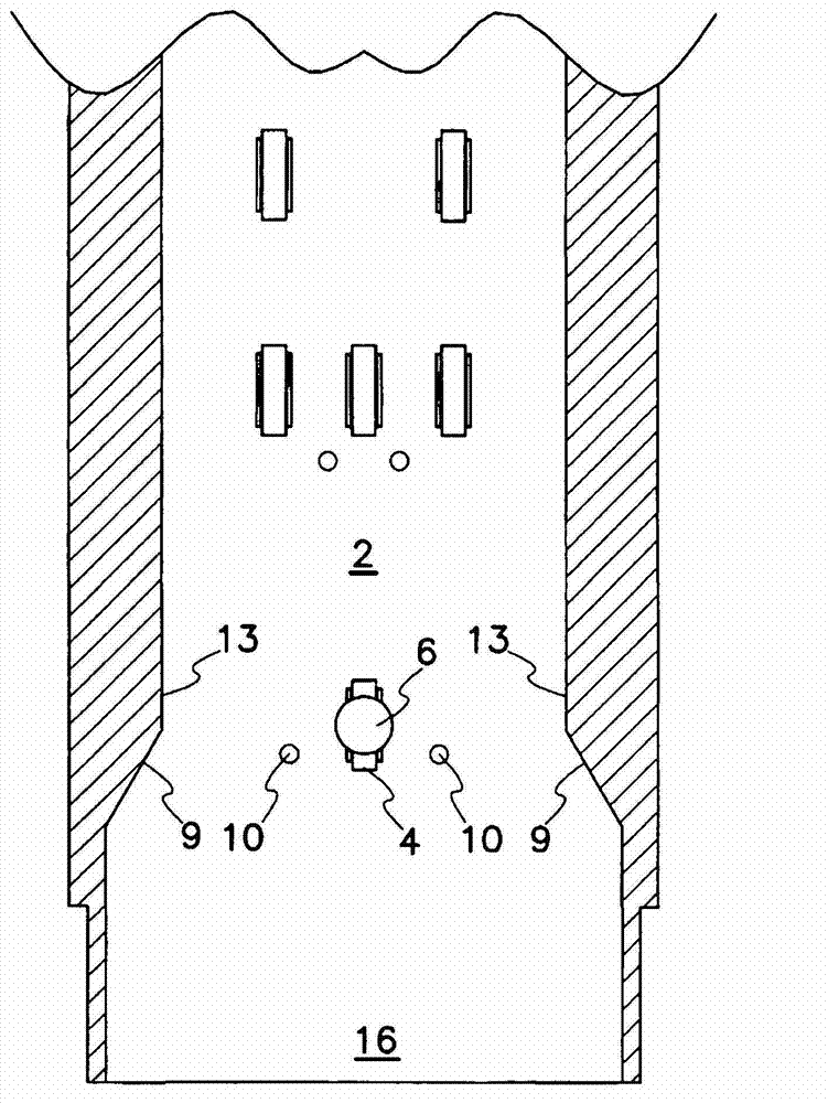
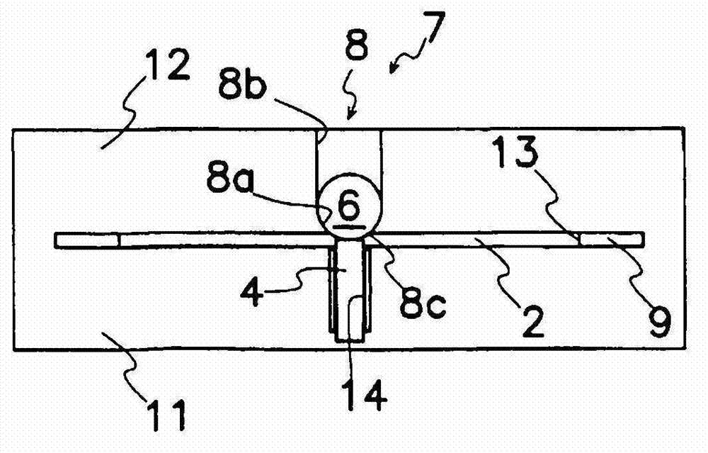
[0035] Figures 1 to 7 A first embodiment of the note feeder according to the invention is shown. Such as figure 1As shown, the note feeder comprises a lane 2 and a conveyor 3 for feeding notes 1 inserted into the lane 2 as documents. The channel 2 comprises a bottom wall 11, a top wall 12 and side walls 13, all formed of plastic or metal material. The conveyor 3 comprises a friction bearing 4 rotatably mounted in the channel 2, a drive device 5 for driving the friction bearing 4 and means for pushing or pressing the note 1 against the conveyor belt of the friction bearing 4. Heavy device7. Although the shown embodiment exemplifies the use of a friction carrier 4 using a conveyor belt, it coul...


PUM


Abstract

A document transporter has a roller or conveyor belt (4) for driving a bill (1) and a weighting device (7) for pressing the bill (1) against the roller/belt (4). The weighting device (7) includes a ball (6) weighting the bill (1) and a holder (8) rotatably holding the ball (6). The device (7) may further include a spring (15) pressing the ball (6) against the roller/belt (4). The passageway (2) into which the bill (1) is inserted is enclosed by a bottom wall (11), a top wall (12) and side walls (13). The side walls (13) have tapered surfaces (9) at the inlet (16) to the passageway (2). A pair of guide rollers (22) rotatably mounted on the side walls (13) guides the bill (1) by engaging the side edges of the bill (1). The bill (1) fed to the transporter is automatically centered.

Description

technical field [0001] The present invention relates to a document feeder for conveying documents, such as receipts, along and in alignment with a lane. Background technique [0002] A known bill feeder includes alignment or centering means for automatically aligning the bills with the channel when the bills are inserted into the channel skewed or inclined from the longitudinal central axis of the channel. For example, Patent Document 1 listed below discloses a self-aligning conveying device for various media, which includes a channel and a plurality of wheels aligned substantially parallel to the side walls of the channel, wherein at least one wheel has a shape The surface of the media is driven in an intermittent manner in a direction longitudinal to the channel to substantially align the media with the sidewalls as the media rotates freely about each rotor. In this mechanism, the medium is driven intermittently to bring the surface of the runner into contact with the med...

Claims


Application Information

Patent Timeline
IPC IPC(8): B65H9/00B65H5/06
CPCB65H2404/611B65H2404/71B65H2404/15B65H2701/1912B65H5/36B65H5/062B65H5/025B65H9/101B65H2404/741B65H2404/54B65H9/16
Inventor 伊藤健一
Owner JAPAN CASH MASCH CO LTD
Why Eureka
Try Eureka