Method for automated determination of an optimally parameterized scatterometry model

A scatterometry, fixed-parameter technique, applied in the field of automatic selection of floating parameter sets

Active Publication Date: 2013-04-03
KLA TENCOR TECH CORP
View PDF8 Cites 17 Cited by
  • Summary
  • Abstract
  • Description
  • Claims
  • Application Information

AI Technical Summary

Problems solved by technology

Taking further into account the diversity of measurement acquisition points typical in semiconductor processing and the frequency of process changes that

Method used


Image

  • Method for automated determination of an optimally parameterized scatterometry model
  • Method for automated determination of an optimally parameterized scatterometry model
  • Method for automated determination of an optimally parameterized scatterometry model

Examples


Embodiment Construction

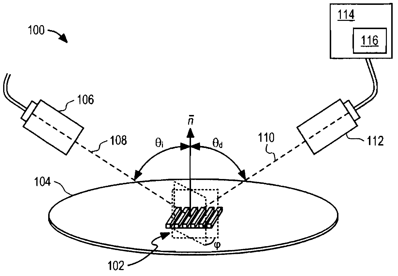
[0033] In the following description, numerous details are set forth. It will be apparent to those skilled in the art that the present invention may be practiced without these specific details. For example, although the method of the present invention is described in the context of scatterometry for diffraction grating parameter measurements, it should be understood that the method can be readily adapted to other situations and applications by one of ordinary skill in the art.

[0034] In some instances, well-known methods and devices are shown in block diagram form and have not been described in detail in order not to obscure the present invention. Reference throughout this specification to an "embodiment" means a particular characteristic, structure, function, or embodiment-related described feature that is included in at least one embodiment of the present invention. Therefore, the appearances of the phrase "in an embodiment" in various places in this specification do not r...


PUM


Abstract

Provided is an automated determination of an optimized parameterization of a scatterometry model for analysis of a sample diffracting structure having unknown parameters. A preprocessor determines from a plurality of floating model parameters, a reduced set of model parameters which can be reasonably floated in the scatterometry model based on a relative precision for each parameter determined from the Jacobian of measured spectral information with respect to each parameter. The relative precision for each parameter is determined in a manner which accounts for correlation between the parameters for a combination.

Description

[0001] Cross References to Related Applications [0002] This application claims the benefit of U.S. Patent Application No. 12 / 841,932 (Attorney Docket No. 8536P005), entitled "Method for Automatically Determining Optimal Parameterized Scatterometric Models," filed July 22, 2010, The entire content of this application is hereby incorporated by reference for all purposes. technical field [0003] Embodiments of the present invention relate to scattering, in particular to methods and systems for automatically selecting a set of floating parameters. Background technique [0004] Optical measuring technology generally refers to the possibility, like scatterometry, of providing features with workpiece parameters during the manufacturing process. In practice, light is irradiated directly on a periodic grating formed on a workpiece and the spectrum of the reflected light is measured and analyzed to characterize the grating parameters. Characterization parameters can include criti...

Claims


Application Information

Patent Timeline
IPC IPC(8): G01N21/47G01N21/27
CPCG03F7/70616G03F7/70625G01N21/27G01N21/47
Inventor J·弗恩斯J·J·亨奇S·科马罗夫T·德兹拉
Owner KLA TENCOR TECH CORP
Why Eureka
Try Eureka