Reactor box chamber cleaning using molecular fluorine

A technology of reaction chamber and molecular fluorine, applied in the field of cleaning reaction chamber, can solve the problems of low efficiency of cleaning chamber and low quality efficiency, etc.

Inactive Publication Date: 2013-04-03
LINDE AG
View PDF7 Cites 2 Cited by
  • Summary
  • Abstract
  • Description
  • Claims
  • Application Information

AI Technical Summary

Problems solved by technology

Finally, the multiple reaction pathways available to fluorine-containing gases (which tend to dominate especially at commercially viable pressures and activation powers) lead to inefficiencies in the use of these compounds for chamber cleaning
Therefore, the use of these gases results in very low mass efficiency

Method used


Image

  • Reactor box chamber cleaning using molecular fluorine
  • Reactor box chamber cleaning using molecular fluorine

Examples


Embodiment Construction

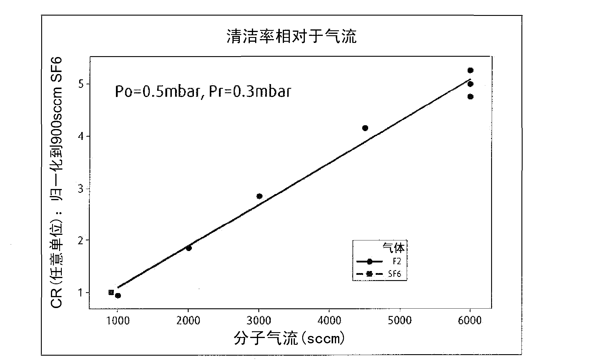
[0013] The present invention uses molecular fluorine for reaction chamber cleaning. In the present invention, it is shown that fluorine radicals generated by separating molecular fluorine are very efficient cleaning gases. The separation energy required for molecular fluorine is relatively low and can be provided by the RF power source already provided in the reaction chamber, ie the RF power source used to separate the deposition precursors. No remote plasma activation is required, so no additional equipment is required.

[0014] figure 1 is for molecular fluorine and SF 6 Graphs of both showing the effect on the cleaning rate of the reaction chamber based on the cleaning gas flow rate. in particular, figure 1 It was shown that molecular fluorine will efficiently clean chambers based on the concept of a reactor enclosed in a vacuum chamber, such as a reaction chamber or a plasma chamber, such as is commercially available from Oerlikon. In these types of chambers, the out...


PUM


Abstract

Methods and apparatus for the cleaning reactor box chambers using molecular fluorine as the cleaning material. The molecular fluorine is dissociated in-situ in the chamber using the chamber RF power source. An exemplary method for of cleaning a reactor box chamber may comprise the steps: introducing molecular fluorine to the chamber; dissociating the molecular fluorine to create fluorine radicals; allowing the fluorine radicals to react with unwanted deposits in the chamber; and removing the resultant gas from the chamber.

Description

technical field [0001] The present invention relates to a new method and apparatus for cleaning reaction chambers. Background technique [0002] Plasma deposition chambers (also known as "reactor boxes" or "plasma chambers") are used to deposit thin films primarily for photovoltaic applications and devices. These chambers are especially useful for forming thin films for solar panels, TFT display panels and plasma display panels. For example, a reaction chamber is described in US Pat. No. 4,798,739 (Schmitt) with a low pressure vessel placed within an airtight chamber, where the airtight chamber is at a lower pressure than the low pressure vessel. The reaction chamber is for performing plasma deposition onto at least two substrates spaced in a substantially parallel relationship within the vessel. To achieve the decomposition of the gaseous reactants in the container, at least one perforated electrode generating a polarized plasma is inserted between the substrates. [000...

Claims


Application Information

Patent Timeline
Patent Type & Authority Applications(China)
IPC IPC(8): H01J37/32
CPCH01J37/3244B08B7/00H01J37/32862C23C16/4405H01J37/32
Inventor J-C·西高S·彼得里P·A·斯托克曼O·尼尔灵
Owner LINDE AG
Why Eureka
Try Eureka