Superfine grinder with slag remover
A technology of ultra-fine pulverizers and crushing chambers, applied in grain processing, etc., can solve the problems of limited service life, great difference between usage and unit energy consumption, and inconvenient maintenance, so as to reduce equipment energy consumption, long service life, and easy maintenance convenient effect
- Summary
- Abstract
- Description
- Claims
- Application Information
AI Technical Summary
Problems solved by technology
Method used
Image

Examples
Embodiment Construction
[0017] The present invention will be further described below in conjunction with the accompanying drawings and embodiments.
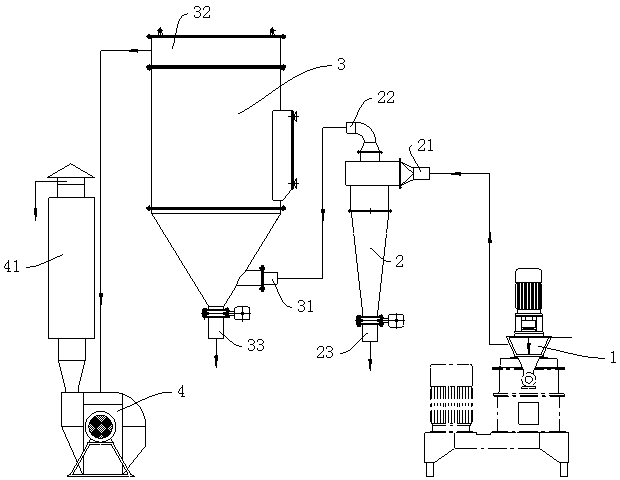
[0018] see figure 1 The micropowder preparation device shown includes an ultrafine pulverizer 1 , a cyclone dust collector 2 , a bag dust collector 3 , and an induced draft fan 4 .
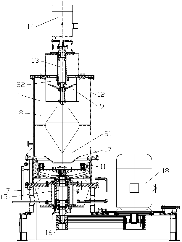
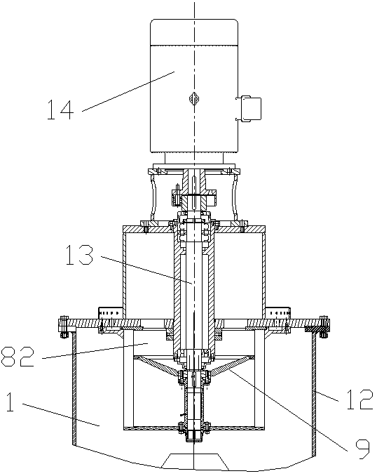
[0019] see figure 2 The shown ultrafine pulverizer 1 includes a casing 12, a feeding pipe 5 connected to the casing for sending pre-crushed materials into the crushing chamber, a discharge port 6, and an air inlet chamber 7 with a lower part in the casing. , The crushing and grading chamber 8 in the upper part.
[0020] The crushing and classifying chamber 8 includes a crushing chamber 81 and a classifying chamber 82 . A classifying impeller 9 is arranged in the crushing and classifying chamber 8 . The upper part of the classifying impeller is a classifying chamber 82, and the lower part is a crushing chamber 81. A crushing disc 10 is arranged in the crushing chamber....
PUM
 Abstract
Description
Claims
Application Information