Power control system of electrical vehicle and charging and discharging method of electrical vehicle

A power control system and electric vehicle technology, applied in electric vehicles, electric traction, control drive, etc., can solve the problems of abnormal operation of components, whether the vehicle components are in normal operation, the charging performance of the battery module 10 is reduced, and the coordination is reduced, so as to achieve simplification Circuit design mode, simple power control mode, and the effect of improving operation coordination

Active Publication Date: 2013-04-10
KYMCO +1
View PDF6 Cites 7 Cited by
  • Summary
  • Abstract
  • Description
  • Claims
  • Application Information

AI Technical Summary

Problems solved by technology

If the time required for the preparatory work of each component is deliberately reduced in the design, it is likely that the coordination between the components will be greatly reduced, and the components will operate abnormally (for example, the electronic control unit cannot determine whether the vehicle components are operating normally, resulting in a crash. or enable the wrong component drive mode), life shortening, or even system damage
[0005] With such a structure, during the charging operation, the whole system must be in the key-on state of the switch module 20, so most of the electronic components of the vehicle will be in the state of receiving power and consume the supplementary power of the system, which greatly reduces the charging performance of the battery module 10
Moreover, the system consumes power while charging, which will make the power balance of the system quite unstable, and then consume the life of vehicle parts

Method used


Image

  • Power control system of electrical vehicle and charging and discharging method of electrical vehicle
  • Power control system of electrical vehicle and charging and discharging method of electrical vehicle
  • Power control system of electrical vehicle and charging and discharging method of electrical vehicle

Examples


Embodiment Construction

[0022] The preferred embodiments of the present invention are described in detail as follows with reference to the accompanying drawings.

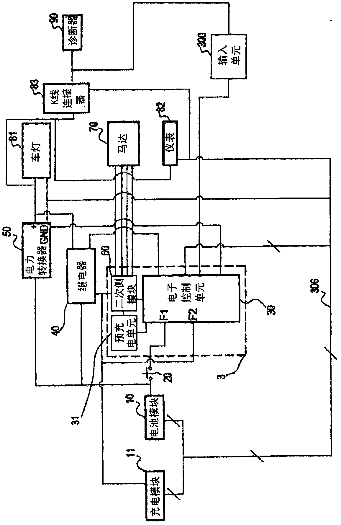
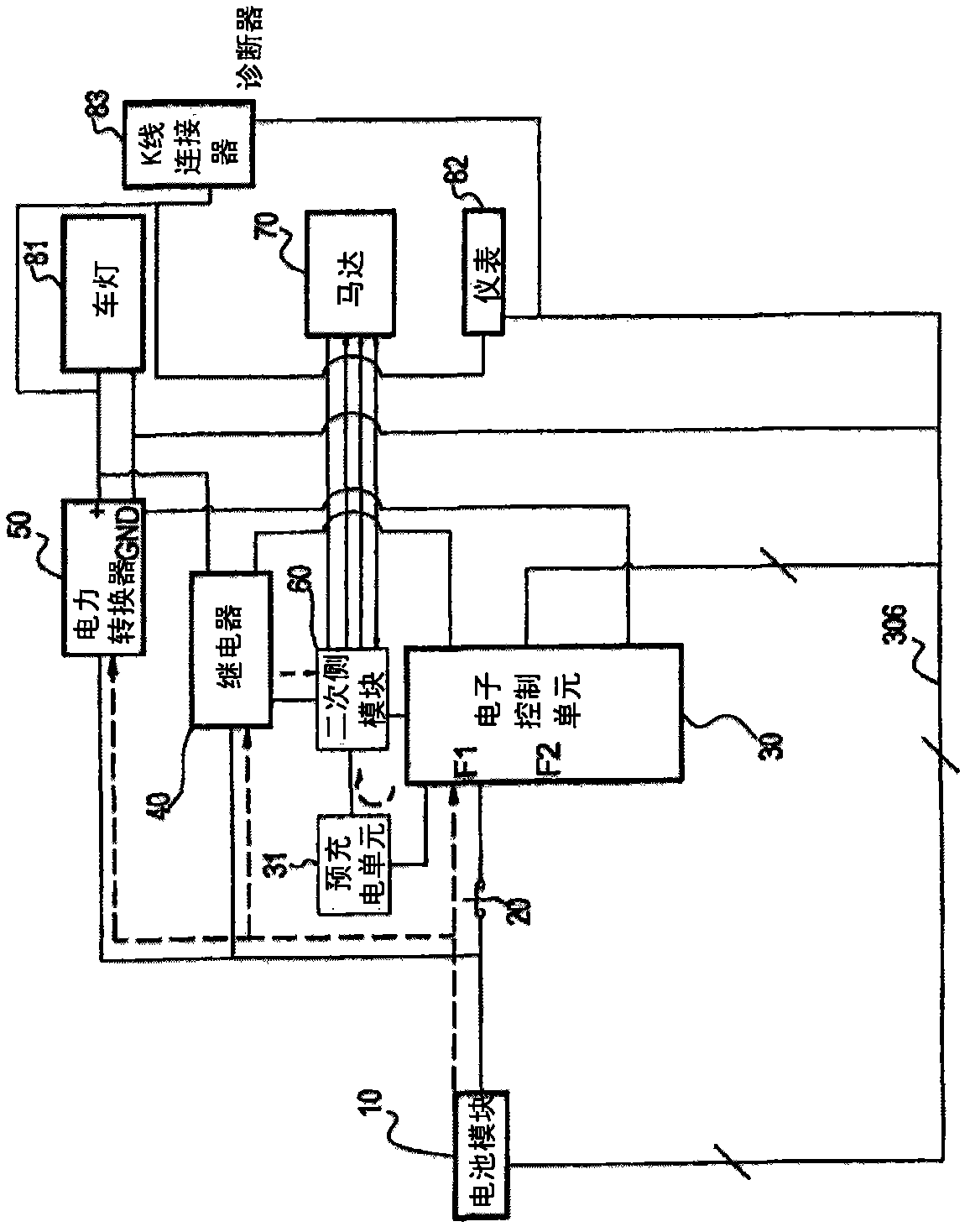
[0023] First please refer to figure 2 A schematic diagram showing the first system architecture of an embodiment of the power control system of an electric vehicle according to the present invention. Please also see image 3 A schematic diagram showing the discharge behavior of the embodiment of the power control system of the electric vehicle of the present invention.

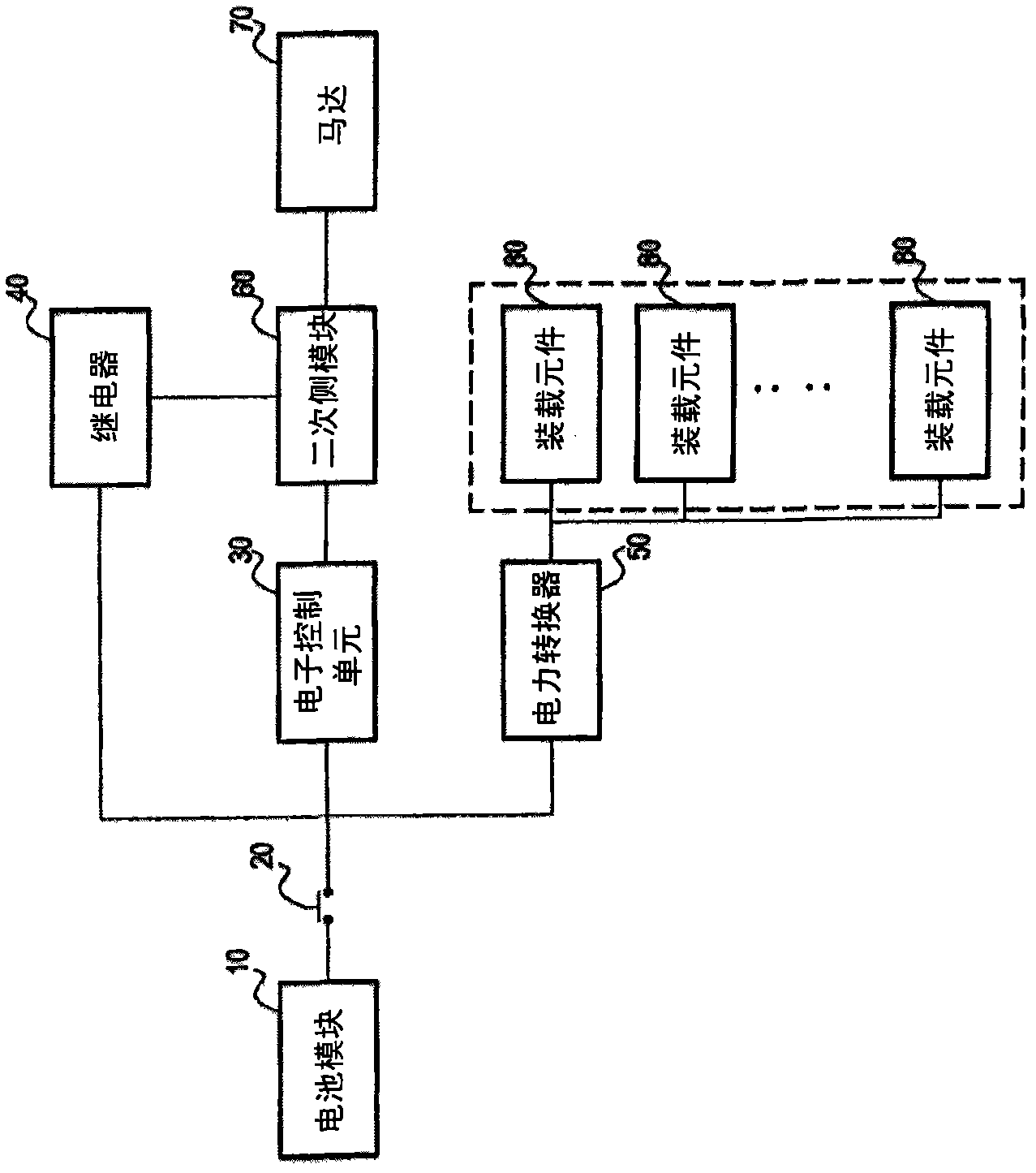
[0024] The system includes a battery module 10 , a switch module 20 , an electronic control unit 30 , a secondary side module 60 , a pre-charging unit 31 , a relay 40 and a power converter 50 .

[0025] The battery module 10 is electrically connected to the switch module 20 , the relay 40 and the power converter 50 , wherein the power-taking terminals of the relay 40 and the power converter 50 are electrically connected to the circuit between the switch module 20 and th...


PUM


Abstract

The invention discloses a power control system of an electrical vehicle and a charging and discharging method of the electrical vehicle. The system comprises a motor, a battery module, a power converter, a relay, a secondary side module, an electronic control unit, a pre-charging unit and a key switch module, wherein the electronic control unit is electrically connected with the battery module when the key switch module is conducted, and is used for controlling the pre-charging unit to pre-charge the secondary side module and controlling the driving of the power converter and the relay so as to finish power supplying of the battery module to drive the motor and the discharging control actions of parts relevant with the electrical vehicle. The electronic control unit is electrically connected with a charging module and runs with power, and is used for controlling the actions of the relay when the key switch module is in disconnection and controlling the charging actions of the charging module on the battery module.

Description

technical field [0001] The present invention relates to a power control system, in particular to a power control system in which electric vehicle components controlled by an electronic control unit conduct power to complete battery charging or discharging. Background technique [0002] see figure 1 Shown is a schematic block diagram of a power control system of a prior art electric vehicle. In the prior art, a battery module (Battery Module) 10 is directly connected to a switch module (Key switch module) 20, and the switch module 20 is then electrically connected to an electronic control unit (Electronic Control Unit, ECU) 30, a relay (Relay) for receiving a large current ) 40 and a power converter (such as DC / DC Power Converter) 50 for voltage regulation. The secondary side module (Second Side Module) 60 is electrically connected to the electronic control unit (Electronic Control Unit, ECU) 30, the relay 40 and the motor (Motor) 70, and the power converter 50 is electrica...

Claims


Application Information

Patent Timeline
Patent Type & Authority Applications(China)
IPC IPC(8): B60L15/00B60L11/18
CPCY02T10/7022Y02T10/7005Y02T10/70
Inventor 许永昌纪顺得黄宏耀曾建评袁德威李韦莹林为腾吴孟通
Owner KYMCO
Why Eureka
Try Eureka