Permanent magnet stepping motor and electronic device

A permanent magnet step and stator technology, which is applied in the direction of electrical components, electromechanical devices, electric components, etc., can solve the problem of increasing the gap between cylindrical electric terminals and eliminating the difficulty of circuit board welding, increasing processing costs and defect rates, and affecting terminal pins. Stability and other issues, to achieve the effect of facilitating modular applications, solving plane scratches, and improving welding efficiency

Active Publication Date: 2021-04-30
NEW SHICOH MOTOR CO LTD
View PDF4 Cites 2 Cited by
  • Summary
  • Abstract
  • Description
  • Claims
  • Application Information

AI Technical Summary

Problems solved by technology

The conventional process is to use the auxiliary jig to protect the cylindrical electric terminal when the gap is in place. The defect of this process is that although it can solve the limit limit protection when the gap is eliminated, the gap on this jig Extreme protection, frequent use has wear and tear on the above-mentioned plane, and the design is unreasonable
[0005] Secondly, when the cylindrical electric connection terminal and the circuit board are welded and connected, the gravity of the circuit board on the cylindrical electric connection terminal at this time will cause compressive damage to the cylindrical electric connection terminal wound on the terminal pin; in addition , in the process of soldering the circuit board, it will cause heat fusion to the plane above the terminal of the winding tube, which will affect the stability of the terminal pin
[0006] The problems in the above-mentioned prior art increase the difficulty of eliminating the clearance of the cylindrical electrical terminals and welding the circuit board, which increases the processing cost and defective rate

Method used


Image

  • Permanent magnet stepping motor and electronic device
  • Permanent magnet stepping motor and electronic device
  • Permanent magnet stepping motor and electronic device

Examples


Embodiment approach

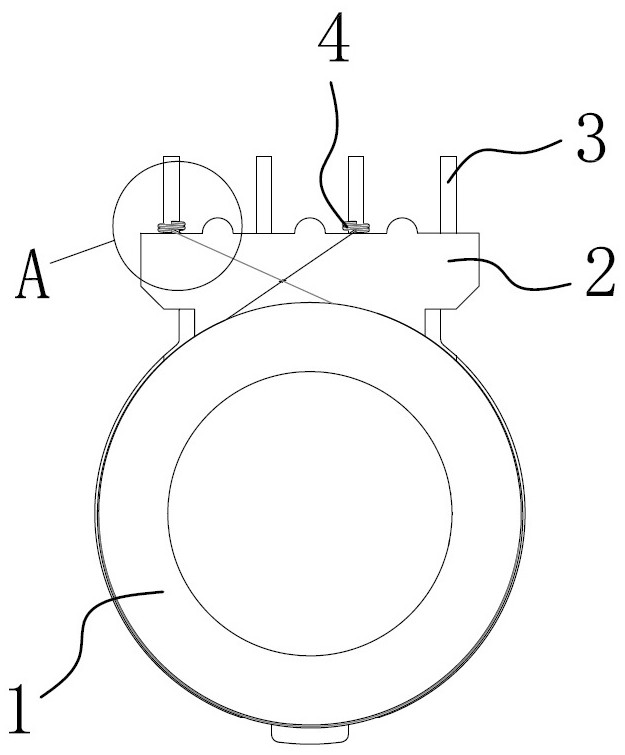
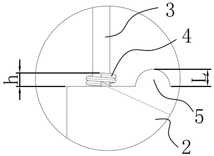
[0069] The protruding anti-damage structure 5 is connected to the protruding platform 2 and protrudes from the end surface of the protruding platform 2 provided with the terminal pin 3;

[0070] The convex height h of the convex damage prevention structure 5 from one end surface of the convex platform 2 to the highest point of the convex damage prevention structure 5 is equal to or greater than the axial direction of the conductive terminal 4 after being axially compressed into place. Length L.

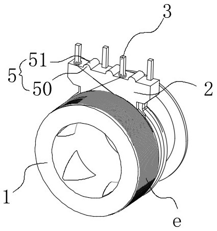
[0071] Such as Figure 10 As shown, the motor also includes a rotor c, which passes through the stator b and the rotor c can rotate relative to the stator b; after the coil e of the stator b is energized, it cooperates with the magnetic field of the rotor c to make the rotor c rotate at a rotation angle of The actual control angle is set.

[0072] Such as Figure 4-5 As shown, the motor also includes a circuit board 6, on which there is an insertion hole 60 for inserting the termin...

Embodiment 2

[0102] The structure and principle of this embodiment are basically the same as those of Embodiment 1, the difference is that: the protruding anti-injury boss 50 is in the shape of a column, which is directly arranged on one end surface of the above-mentioned outer protruding platform 2 .

[0103] Of course, it can also be a columnar convex anti-injury boss and a strip-shaped anti-injury boss arranged on one end surface of the above-mentioned outer convex platform 2, and this embodiment does not carry out the anti-injury for different shapes of the outer convex Bosses are exhausted.

Embodiment 3

[0105] The structure and principle of this embodiment are basically the same as those of Embodiment 1, the difference is that the protruding anti-injury boss 50 is distributed along the length direction of one end surface of the above-mentioned outer protruding platform 2 . Pay attention to avoid enamelled copper wires when distributing.


PUM


Abstract

The invention relates to a permanent magnet stepping motor and an electronic device, and solves the technical problem that the wiring end of an existing stator terminal is easy to damage. The permanent magnet stepping motor comprises a stator, wherein the stator is cylindrical; aprotruding boss which is connected to the stator; a terminal pin of which the inner end is embedded and fixed in the outer boss, and the outer end penetrates out of one end face, away from the stator, of the outer boss; a conductive wiring end which is wound at one end, close to the outer boss, of the terminal pin and is connected with a coil on the stator; a rotor which penetrates through the stator and can rotate relative to the stator; and a protruding anti-damage structure which is connected to the protruding boss and protrudes out of the end face, provided with the terminal pin, of the protruding boss. The protruding height of the protruding anti-damage structure from one end face of the protruding boss to the highest protruding point of the protruding anti-damage structure is equal to or larger than the axial length of the conductive wiring end after the conductive wiring end is axially compressed in place. The invention has the advantage that the wiring end can be protected.

Description

technical field [0001] The invention belongs to the technical field of miniature permanent magnet stepping motors, in particular to a permanent magnet stepping motor and electronic equipment. Background technique [0002] The miniature permanent magnet stepper motor is a kind of stepper motor. The stator is a claw-shaped pole tooth formed by sheet metal stamping, and the rotor is a permanent magnet steel. The advantages of miniature permanent magnet stepper motors are simple structure, convenient driving, adjustable speed, high precision and low noise. [0003] Miniature permanent magnet stepper motors are widely used in monitoring systems, automatic control, office, communication and scanning fields and other electronic equipment fields; for example, monitoring systems use optical components, such as lenses, etc. Equipped with micro stepper motors to realize control of optical components drive. [0004] In the original miniature permanent magnet stepper motor, the end sur...

Claims


Application Information

Patent Timeline
Patent Type & Authority Applications(China)
IPC IPC(8): H02K37/14H02K3/50H02K7/116
CPCH02K3/50H02K7/1166H02K37/14
Inventor 柯曾松
Owner NEW SHICOH MOTOR CO LTD
Why Eureka
Try Eureka