Novel double-braking rim driving device

A wheel-side drive, double-brake technology, applied in the direction of transmission parts, brake types, brake actuators, etc., can solve problems such as damage, torque increase, friction and high temperature deformation, etc., to avoid action failure and transmission torque increase. Large, long service life effect

Active Publication Date: 2013-04-10
INI HYDRAULIC
View PDF5 Cites 23 Cited by
  • Summary
  • Abstract
  • Description
  • Claims
  • Application Information

AI Technical Summary

Problems solved by technology

However, the multiple sets of steel sheets and multiple sets of dynamic friction plates of the service brake are mainly installed outside the support sleeve, especially the multiple sets of dynamic friction plates are all installed in the splines provided outside the support sleeve, and the multiple sets of dynamic friction plates are pressed by the piston during work. The steel plate and multiple sets of dynamic friction plates are used to brake the supporting sleeve, and then achieve the purpose of braking the inner gear housing to form a brake. During the braking process, since the inner gear housing is used as the active part to drive the bearing sleeve to rotate, Directly tightening the support sleeve will increase the torque connected between the support sleeve and the internal gear housing, which cannot achieve a good braking effect
[0004] At the same time, in the technical solution disclosed in the above-mentioned patent, multiple sets of steel plates and multiple sets of dynamic friction plates are directly arranged alternately, and there is no corresponding cooling device on the service brake. Therefore, during the braking process, due to sometimes Under the influence of factors such as the viscosity of the hydraulic oil between the steel plate and the dynamic friction plate, and the high-temperature deformation of the friction between the steel plate and the dynamic friction plate, when the service brake is released, the adjacent steel plate and the dynamic friction There is often a phenomenon that the discs cannot be completely disengaged, which causes the braking failure of the service brake and brings potential safety hazards
The service brake does not have a cooling device, and the large amount of heat generated during the service brake will also cause damage to various components.

Method used


Image

  • Novel double-braking rim driving device
  • Novel double-braking rim driving device
  • Novel double-braking rim driving device

Examples


Embodiment Construction

[0020] The embodiments of the present invention will be described in detail below according to the above-mentioned drawings.

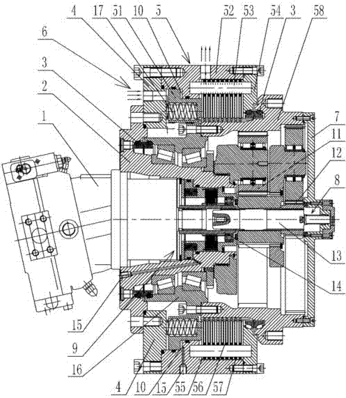
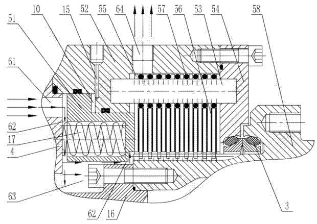
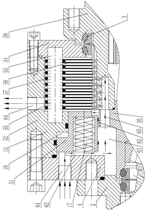
[0021] like Figure 1~Figure 5 As shown, 1. Hydraulic motor, 2. Support seat, 3. Heavy-duty floating seal ring, 4. Support plate, 5. Service brake, 51. Piston, 52. Shell, 53. Connecting rod, 54. Mounting plate, 55 .Steel sheet, 56. Moving friction plate, 57. Rubber ring, 58. Internal gear housing, 6. Cooling circulation system, 61. Cold oil inlet, 62. Oil passage gap, 63. Oil chamber, 64. Hot oil outlet, 65. Oil hole, 7. Cover plate, 8. Manual release device, 81. Release shaft, 82. Return spring, 83. Cover, 9. Parking brake, 91. Collar, 92. Fixed plate, 93. Piston sleeve, 94. Wet brake pad set, 95. Fixed sleeve, 96. Bearing, 10. Oil chamber, 11. Secondary planetary reduction mechanism, 12. Primary center wheel, 13. Connecting shaft, 14. Spline Connection sleeve, 15. oil delivery channel, 16. support sleeve, 17. push spring.

[0022] New wheel drive ...


PUM


Abstract

The invention discloses a novel double-braking rim driving device, and relates to a double-braking device for tire parking braking and driving braking. The novel double-braking rim driving device comprises a supporting base, a hydraulic motor, a planetary gear speed reducer, a parking brake, a driving brake and the like, wherein a plurality of groups of movable friction sheets of the driving brake are respectively embedded into splines arranged outside an inner gear shell of the planetary gear speed reducer; a plurality of groups of steel sheets are simultaneously connected onto a connecting rod in series; and a rubber ring is arranged between each steel sheet and each movable friction sheet, which are adjacent. The braking on the inner gear shell is directly carried out so that the braking is more reliable and safer; elastic auxiliary steel sheets of the rubber rings and the movable friction sheets are completely separated, so that movement failure is prevented from happening; the driving brake is additionally provided with a cooling circulating system, so that heat generated by the driving braking can be eliminated, parts are prevented from being damaged at a high temperature, and the service life is prolonged; and the improved rim driving device also has the advantages of compact structure, high working efficiency, large transmission torque and the like.

Description

technical field [0001] The invention relates to a wheel-side driving device, in particular to a novel wheel-side driving device with double brakes. Background technique [0002] At present, the traditional wheel drive device is generally composed of a support seat, a support sleeve, a hydraulic motor, a multi-stage planetary gear reducer, an internal gear housing, and a parking brake. The parking brake can only work after the tire stops. , and when the tires are running normally, due to the faster walking speed of the wheel drive, it is necessary to add a pair of shoe-type service brakes or disc-type service brakes to the tires to realize the service braking function. The service brakes are usually It is directly installed on the multi-stage planetary gear reducer along the axial direction. As a result, the tires with limited installation space are more stretched, which not only reduces the working efficiency of the driving device, affects the transmission torque, but also ...

Claims


Application Information

Patent Timeline
Patent Type & Authority Applications(China)
IPC IPC(8): F16H57/10F16D55/24F16D65/14F16D121/04F16D125/02F16D125/08
Inventor 胡世璇江峰
Owner INI HYDRAULIC
Why Eureka
Try Eureka