Dodging lens, backlight module using dodging lens and display device

A technology of uniform light lens and backlight module, which is applied to lighting devices, fixed lighting devices, components of lighting devices, etc., can solve the problems of difficult thin design of backlight modules, expensive uniform light lens, etc., and achieve the effect of light output. Good, cost reduction, product cost reduction effect

Active Publication Date: 2015-01-07
BOE TECH GRP CO LTD +1
View PDF3 Cites 0 Cited by
  • Summary
  • Abstract
  • Description
  • Claims
  • Application Information

AI Technical Summary

Problems solved by technology

At present, almost all uniform light lenses in the market are circular, and are mainly used in direct LED backlight modules, but the price of the uniform light lens is quite expensive, and the circular uniform light lens is difficult to Realize the thin design of the backlight module, so it is difficult to apply this uniform light lens in the corner backlight module

Method used


Image

  • Dodging lens, backlight module using dodging lens and display device
  • Dodging lens, backlight module using dodging lens and display device
  • Dodging lens, backlight module using dodging lens and display device

Examples


Embodiment 1

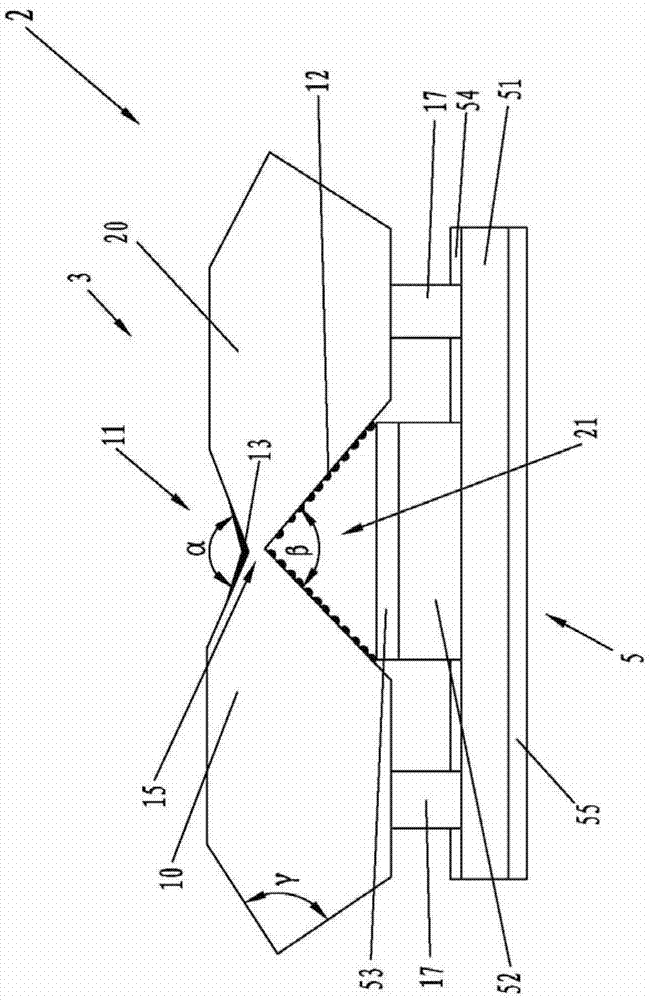
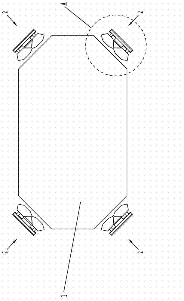
[0037] Such as figure 1 , image 3 , Figure 4 As shown, the embodiment of the backlight module using uniform light lens of the present invention includes a light guide plate 1 and a light source device 2 disposed on the side of the light guide plate 1 . The light source device 2 comprises the uniform light lens 3 of the present invention and the light source 5 arranged inside the second V-shaped groove 21 of the uniform light lens 3, and the opening of the first V-shaped groove surface 11 of the uniform light lens 3 faces the opening of the light guide plate 1. side.

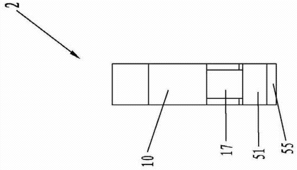
[0038] combine figure 2 As shown, the homogenizing lens 3 includes a first sheet 10 and a second sheet 20 both of which are hexagonal. The first sheet 10 and the second sheet 20 are located at the same height and are arranged side by side. One corner of the first sheet 10 is connected to a corresponding corner of the second sheet 20 to form a second sheet above the connection point. A V-shaped groove 11 a...

Embodiment 2

[0072] The specific structure of the homogenizing lens of the present invention should match the model selected by the LED lamp, that is, the specific size of the homogenizing lens varies with the size of the selected LED.

[0073] Figure 5 The specific structural dimensions of another embodiment of the uniform light lens of the present invention are shown. The difference between the uniform light lens 3' of this embodiment and the uniform light lens 3 in the first embodiment is that the first V-shaped groove 11 ' and the second V-shaped groove 21' are circular arc grooves with a circular arc cross section.

[0074] In the uniform light lens 3', the first sheet 10' and the second sheet 20' are left-right symmetrical with the vertical central axis 70' as the axis of symmetry.

[0075] The thickness of the homogenizing lens 3' of the present embodiment is consistent with that of the LED lamp 52', both being 1.4 millimeters. The groove bottom of the first V-shaped groove 11' i...


PUM

PropertyMeasurementUnit
thicknessaaaaaaaaaa

Abstract

The invention provides a dodging lens, a backlight module using the dodging lens and a display device. The dodging lens comprises a first sheet body and a second sheet body, wherein the first sheet body is connected with the second sheet body so as to form a first V-shaped slot and a second V-shaped slot above a connecting point. The backlight module using the dodging lens comprises a light guide plate and a light source device, and the light source device comprises the dodging lens provided by the invention and a light source. The display device comprises the backlight module using the dodging lens. The dodging lens can satisfy the thinned design requirements for the backlight module; and the shaping technology is simple, and the cost is low. Because the backlight module using the dodging lens adopts the dodging lens provided by the invention, the light emitting effect is better, and the cost is greatly reduced. Because the display device adopts the backlight module provided by the invention, the cost of a product can be greatly reduced, and the quality of the product can be greatly improved.

Description

technical field [0001] The invention relates to the field of display technology, in particular to a uniform light lens, a backlight module and a display device using the light uniform lens. Background technique [0002] The backlight module is one of the important components of the liquid crystal display. Since the liquid crystal itself does not emit light, the function of the backlight module is to supply sufficient brightness and evenly distributed light source, so that the liquid crystal display can display images normally. At present, the display technology of liquid crystal display has become mature, especially in the design of the backlight module. In addition to being used in liquid crystal display devices such as liquid crystal displays and liquid crystal televisions, backlight modules can also provide light sources for display devices such as digital photo frames, electronic paper, and mobile phones. [0003] The backlight module is divided into an edge-type backli...

Claims


Application Information

Patent Timeline
Patent Type & Authority Patents(China)
IPC IPC(8): G02F1/13357F21V5/04F21S8/00F21Y101/02
Inventor 陈秀云尹大根朱红丽
Owner BOE TECH GRP CO LTD
Why Eureka
Try Eureka