Optical system focal distance detection method

A detection method and optical system technology, applied in the field of optics, can solve the problems of long focal length optical instruments, image quality degradation, deviation, etc.

Active Publication Date: 2013-04-10
CHANGCHUN INST OF OPTICS FINE MECHANICS & PHYSICS CHINESE ACAD OF SCI
View PDF5 Cites 9 Cited by
  • Summary
  • Abstract
  • Description
  • Claims
  • Application Information

AI Technical Summary

Problems solved by technology

The actual value of the focal length after the optical system is adjusted has a certain deviation from the design value. Generally, the magnification method and the goniometric method are used to measure the optical system. The theoretical value of the standard deviation of the magnification method is 0.3%, and the theoretical value of the standard deviation of the goniometric method However, in the actual measurement, the focal length of the measured system is affected by many factors such as environmental factors, human factors, technical adjustment level, principle error and reading error, so that the actual measurement error of the focal length of the two methods is not less than 2%
This measurement error has less effect on short focal length lenses, but can be significant on long focal length optics
For lenses with a focal length of more than 1.5m, an error of 2% will cause the image quality to degrade very quickly

Method used


Image

  • Optical system focal distance detection method
  • Optical system focal distance detection method
  • Optical system focal distance detection method

Examples


Embodiment Construction

[0015] The present invention will be described in detail below in conjunction with the accompanying drawings.

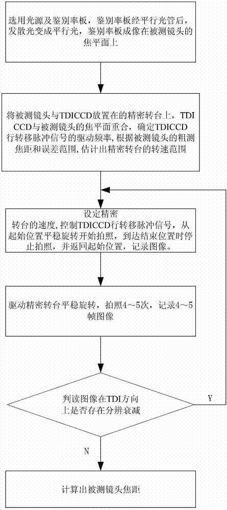
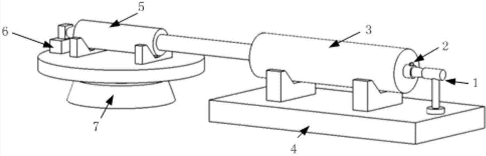
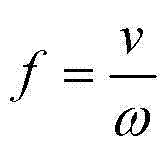
[0016] The focal length detection method of an optical system of the present invention utilizes the principle of image motion velocity matching to detect the focal length, that is, it must be ensured that the moving linear velocity of the moving target at infinity on the focal plane is consistent with the moving linear velocity of the photodetector. Assume that the linear velocity of image movement is v, the focal length of the measured lens is f, and the ratio of the linear velocity of image movement v to the focal length f is the angular velocity . The focal length of the lens under test is a constant value, so the rotational angular velocity ω of a certain image point a Corresponding to only one image moving speed v a , if and only if the moving linear velocity of the photodetector is the same as the image moving linear velocity v a When equal, the image defin...


PUM


Abstract

The invention discloses an optical system focal distance detection method and belongs to the technical field of optics. The method includes the following steps that moire fringes are formed after light of a light source penetrates through a target board and change divergent light of the target light to parallel light after passing through a collimator, and after the parallel light passes through a shot under a test, a target is image-formed on a focal plane of the shot under the test; a time delay and integration charge coupled device (TDICCD) is configurated through a computer, driving frequency fT of a line transfer pulse signal of the TDICCD is confirmed, from image motion linear speed people can know that the driving frequency fT of the line transfer pulse signal has a proportional relation to the image motion linear speed, when the computer controls the TDICCD to start rotation from an initial position, the line transfer pulse signal is sent, images are started to be recorded, when the TDICCD reaches to an ending position, the images are stopped being recorded, and the line transfer pulse signal is stopped being sent. Under the speed, a precise rotating platform is driven to take pictures for 4-5 times, and focal distance of the shot under the test is calculated. The optical system focal distance detection method is high in detection accuracy and widely applied to detection on focal distance of optical system of optical instrument equipment.

Description

technical field [0001] The invention relates to a method for detecting the focal length of an optical system, which belongs to the field of optical technology. Background technique [0002] The focal length of the optical system is one of the main parameters of optical instruments and equipment, and its accuracy directly affects the imaging quality of the equipment. The actual value of the focal length after the optical system is adjusted has a certain deviation from the design value. Generally, the magnification method and the goniometric method are used to measure the optical system. The theoretical value of the standard deviation of the magnification method is 0.3%, and the theoretical value of the standard deviation of the goniometric method However, in the actual measurement, the focal length of the measured system is affected by many factors such as environmental factors, human factors, technical adjustment level, principle error and reading error, so that the actual m...

Claims


Application Information

Patent Timeline
IPC IPC(8): G01M11/02
Inventor 刘志明陈黎匡海鹏张雪菲李清军
Owner CHANGCHUN INST OF OPTICS FINE MECHANICS & PHYSICS CHINESE ACAD OF SCI
Why Eureka
Try Eureka