Brightening membrane and backlight module and display device

A technology of backlight module and brightness enhancement film, which is applied in optics, optical components, nonlinear optics, etc., can solve the problem of poor gain effect, achieve the effect of improving gain characteristics and reducing overall thickness

Inactive Publication Date: 2013-04-10
BOE TECH GRP CO LTD +1
View PDF7 Cites 4 Cited by
  • Summary
  • Abstract
  • Description
  • Claims
  • Application Information

AI Technical Summary

Problems solved by technology

There is also a microlens (Microlens) with a brightness-enhancing film. Its viewing angle is worse than the above-mentioned prism sheet, but the light gain effect is not as good as the above-mentioned prism sheet.

Method used


Image

  • Brightening membrane and backlight module and display device
  • Brightening membrane and backlight module and display device
  • Brightening membrane and backlight module and display device

Examples


Embodiment 1

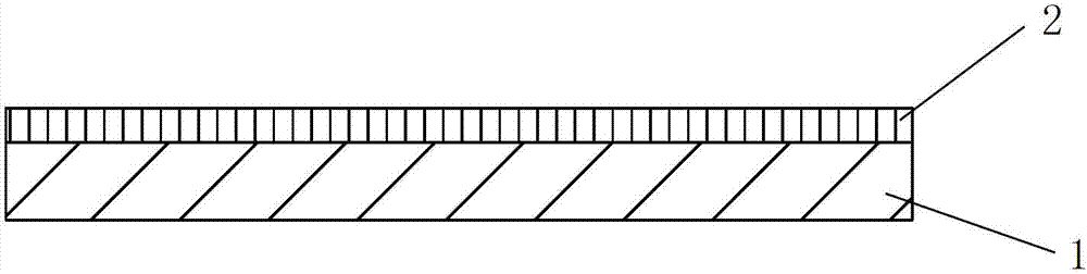
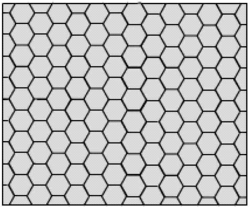
[0029] like figure 1 and refer to Figure 2-Figure 3 As shown, the present invention provides a brightness-enhancing film, including a substrate 1 and a microlens 2 formed on the substrate. The microlens 2 includes: a plurality of optical unit structures, and each optical unit structure is in contact with the substrate. The bottom surface is polygonal, and an arc structure corresponding to the shape of the bottom surface is formed on the bottom surface; each optical unit structure is closely connected with its surrounding adjacent optical unit structures.

[0030] Preferably, the bottom surface of each optical unit structure in contact with the base is a regular hexagon, and each optical unit structure has the same size.

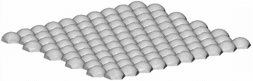
[0031] like Figure 4-Figure 6 As shown, preferably, the arc-shaped structure is a convex lens.

[0032] The diaphragm 41 is made of PET (polyethylene terephthalate), PC (polycarbonate) or PS (polystyrene), preferably made of PET material, and the optical...

Embodiment 2

[0034] The brightness-enhancing film of this embodiment has basically the same structure as that of Embodiment 1, including a substrate 1 and a microlens 2 formed on the substrate. The microlens 2 includes: a plurality of optical unit structures, each optical unit structure and the The bottom surface in contact with the base is polygonal, and an arc structure corresponding to the shape of the bottom surface is formed on the bottom surface; there is no gap between each optical unit structure and its surrounding adjacent optical unit structures.

[0035] The difference is that: the bottom surface of each optical unit structure in contact with the base is an equilateral triangle and the size of each optical unit structure is the same; the arc-shaped structure is a concave lens.

[0036] The diaphragm 41 is made of PET (polyethylene terephthalate), PC (polycarbonate) or PS (polystyrene), preferably made of PET material, and the optical unit structure is made of organic Made of gla...

Embodiment 3

[0038] The brightness enhancing film of this embodiment has basically the same structure as that of Embodiment 1 and Embodiment 2, including a substrate 1 and a microlens 2 formed on the substrate. The microlens 2 includes: a plurality of optical unit structures, each optical The bottom surface of the unit structure in contact with the base is polygonal, and an arc structure corresponding to the shape of the bottom surface is formed on the bottom surface; there is no gap between each optical unit structure and its surrounding adjacent optical unit structures.

[0039] The difference is that: the bottom surface of each optical unit structure in contact with the base is square and the size of each optical unit structure is the same; the arc-shaped structure is a convex lens.

[0040] The diaphragm 41 is made of PET (polyethylene terephthalate), PC (polycarbonate) or PS (polystyrene), preferably made of PET material, and the optical unit structure is made of organic Made of glass...


PUM


Abstract

The invention discloses a brightening membrane which comprises a substrate and a micro lens formed on the substrate, wherein the micro lens comprises a plurality of optical unit structures; the bottom surface, in contact with the substrate, of each optical unit structure is of a polygon shape; an arc-shaped structure which corresponds to the bottom surface in size is formed above the bottom surface; and each optical unit structure is tightly connected with peripheral neighboring optical unit structures. The invention further discloses a backlight module which comprises the brightening membrane. The invention further discloses a display device which comprises the backlight module. The backlight module and the display device provided with the backlight module can improve gain characteristics of light and reduce overall thickness of the device.

Description

technical field [0001] The invention relates to the field of display technology, in particular to a brightness enhancing film, a backlight module and a display device. Background technique [0002] Among flat panel displays, LCDs are devices that do not emit light themselves. It uses a backlight to emit light. The backlight unit includes: a molded frame with a fixing effect; a reflector installed on the bottommost surface for reflecting light to the liquid crystal display panel; a light guide plate arranged on the reflector for guiding light; arranged on the light guide plate and receiving The light source used to emit light between the side walls of the space or under the diffuser plate; the diffuser sheet placed on the light guide plate for uniform light; the prism sheet placed on the diffuser sheet for converging light; used to protect the diffuser Protective film for film and prism film; and other optical films, etc. [0003] The microstructure profile of the prism sh...

Claims


Application Information

Patent Timeline
Patent Type & Authority Applications(China)
IPC IPC(8): G02B3/00G02B1/00G02F1/13357
CPCG02F1/133611G02B3/0056G02F1/133607
Inventor 唐蓉李响邹斌王丹邵喜斌
Owner BOE TECH GRP CO LTD
Why Eureka
Try Eureka