
Remote monitoring and controlling system

A remote monitoring system and remote monitoring technology, applied in the direction of electrical program control, comprehensive factory control, comprehensive factory control, etc., can solve the problems of lack of real-time control of data, control of equipment status, and inability to use units, so as to reduce personnel and equipment management costs. , The effect of optimizing the production process and reducing safety production accidents

Inactive Publication Date: 2013-04-10
WUHAN BEIDOU RUIHUA TECH
View PDF4 Cites 33 Cited by
  • Summary
  • Abstract
  • Description
  • Claims
  • Application Information

AI Technical Summary

Problems solved by technology

For example, the invention patent of application number 200710147826 "energy-saving monitoring system" achieves the purpose of energy saving by monitoring the status of electricity consumption, heat energy, environment, water and gas, etc., and the invention patent of application number 200908154725.3 "remote monitoring system" is The purpose of monitoring is achieved by transmitting the danger signal to the user terminal by the remote monitoring unit installed in the remote place to monitor the situation of the remote place and generate a danger signal if a dangerous situation occurs, but these inventions are not suitable for industrial production and are only Statistics on energy saving and safety status lack real-time control of data, fault alarms, maps and other functions, which cannot enable the user to control the current equipment status

Method used


Image

  • Remote monitoring and controlling system

Examples


Embodiment Construction

[0025] The present invention will be further described below in conjunction with the accompanying drawings and specific embodiments, so that those skilled in the art can better understand the present invention and implement it, but the examples given are not intended to limit the present invention.

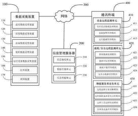
[0026] Such as figure 1 As shown, the remote monitoring system includes a data collection device 100 , an information management server 200 , a communication terminal 400 and a network 300 for connecting the data collection device 100 , the information management server 200 and the communication terminal 400 .

[0027] The data collection device 100 includes a temperature data collection device 110 , a humidity data collection device 120 , a flow data collection device 130 , an energy consumption data collection device 140 , an operating equipment data collection device 150 , an infrared device 160 and a video device 170 .

[0028] The temperature data acquisition device 110...


PUM


Abstract

The invention relates to a remote monitoring and controlling system, in particular to a remote monitoring system for industrial equipment. The remote monitoring and controlling system comprises a data collecting device, an information management server, a communication terminal and a network. The data collecting device is used for collecting data of the monitored equipment and transmitting the data to the information management server or the communication terminal. The information management server is used for receiving, storing and processing the data from the data collecting device and transmitting the data to the communication terminal. The communication terminal is used for receiving and displaying the data of the data collecting device and the data of the information management server. The network is used connecting the data collecting device, the information management server and the communication terminal. The remote monitoring and controlling system can not only carry out remote monitoring, failure warning, energy conservation statistics and data analysis to the industrial equipment, but also maintain, repair and preserve the industrial equipment.

Description

technical field [0001] The invention relates to a remote monitoring system, in particular to a system for remote monitoring of industrial equipment. Background technique [0002] Currently on the market, there are only remote monitoring of street lamps, elevators and other facilities, or energy-saving and safety monitoring of offices and residences, but there is a lack of means and methods for remote monitoring of industrial equipment used in production lines of manufacturing companies. For example, the invention patent of application number 200710147826 "energy-saving monitoring system" achieves the purpose of energy saving by monitoring the status of electricity consumption, heat energy, environment, water and gas, etc., and the invention patent of application number 200908154725.3 "remote monitoring system" is The purpose of monitoring is achieved by transmitting the danger signal to the user terminal by the remote monitoring unit installed in the remote place to monitor ...

Claims


Application Information

Patent Timeline
Patent Type & Authority Applications(China)
IPC IPC(8): G05B19/418
CPCY02P80/10Y02P90/02
Inventor 傅波汪愉曹文静冯济
Owner WUHAN BEIDOU RUIHUA TECH
Learn More