Camshaft adjuster facilities and camshaft adjusters

A technology of camshaft adjuster and camshaft, which is applied in the direction of mechanical equipment, machine/engine, engine components, etc. It can solve the problems of tightening the central screw and difficult operation of the screw head, and achieve the effect of uniform distribution

Inactive Publication Date: 2016-01-06
SCHAEFFLER TECH AG & CO KG
View PDF5 Cites 0 Cited by
  • Summary
  • Abstract
  • Description
  • Claims
  • Application Information

AI Technical Summary

Problems solved by technology

However, this embodiment has the disadvantage that high tightening torques for the screws are required
Furthermore, only relatively little space is available in the area of ​​the screw head of the central screw, making access to the screw head difficult, which makes tightening the central screw even more problematic

Method used


Image

  • Camshaft adjuster facilities and camshaft adjusters
  • Camshaft adjuster facilities and camshaft adjusters

Examples


Embodiment Construction

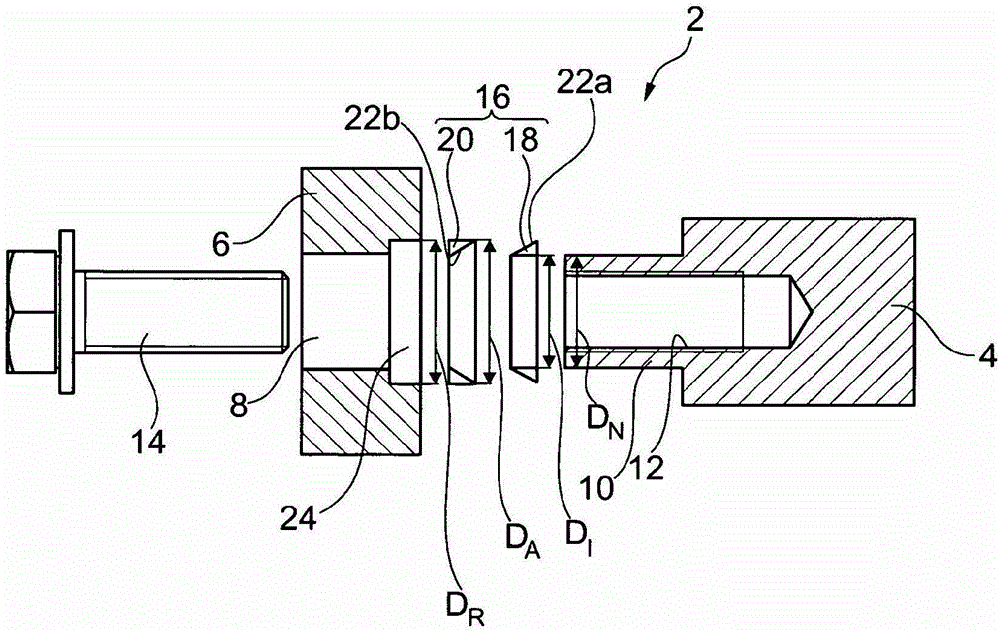
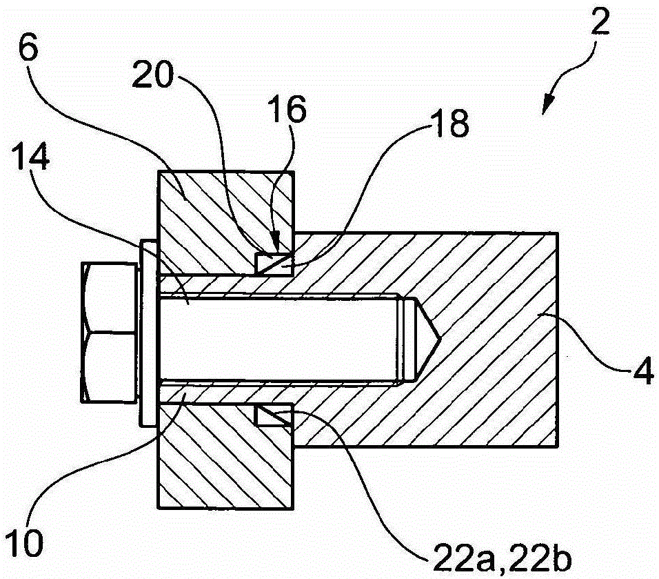
[0020] according to figure 1 and figure 2 The camshaft adjuster arrangement 2 comprises a camshaft 4 and a rotor 6 for a camshaft adjuster not shown in detail here, which is mounted on the camshaft 4 in a rotationally fixed manner. The camshaft adjuster is supplemented by a stator, not shown here, which is arranged concentrically in the rotor 6 .

[0021] The rotor 6 has a central bore 8 . An axially protruding cylindrical shoulder 10 is formed on the camshaft 4 , which is inserted into the central bore 8 in the assembled state. The shoulder 10 is substantially hollow and has an internal thread 12 . The fastening of the rotor 6 on the camshaft 4 takes place via a fastening element, in this case a central screw 14 screwed into the hollow shaft shoulder 10 .

[0022] The tightening torque of the central screw 14 is reduced in such a way that the non-positive connection is converted into a non-positive and frictional connection by using the tensioning sleeve 16 . In this ex...


PUM


Abstract

The camshaft adjuster arrangement (2) comprises a camshaft (4) and a rotor (6) for the camshaft adjuster. The rotor (6) has a central bore (8) for a fastening element (14), via which the rotor is mounted on the camshaft (4) in a rotationally fixed manner. Assembly of the camshaft adjuster arrangement (2) is simplified by the frictional connection between the camshaft (4) and the rotor (6) by means of a tensioning sleeve (16).

Description

technical field [0001] The invention relates to a camshaft adjuster assembly comprising a camshaft and a rotor for the camshaft adjuster. Furthermore, the invention relates to a camshaft adjuster comprising a rotor and a stator arranged coaxially and movable relative to each other. Background technique [0002] In internal combustion engines, especially in gasoline-powered motor vehicle engines, camshafts are used for actuating so-called gas exchange valves. The cams of the camshaft usually rest against a cam follower such as a tappet, a drag rod or a rocker. If the camshaft turns, the cam rolls on the cam follower, which in turn operates the gas exchange valve. Therefore, the position and shape of the cam determine not only the opening duration and opening amplitude of the ventilation valve but also the opening and closing moments of the ventilation valve. [0003] The angular displacement of the camshaft relative to the crankshaft to obtain an optimal control time for d...

Claims


Application Information

Patent Timeline
Patent Type & Authority Patents(China)
IPC IPC(8): F01L1/344F01L1/46
CPCF01L1/3442F01L1/46F01L2303/00Y10T403/7056F01L1/356
Inventor 维尔纳·瓦格纳
Owner SCHAEFFLER TECH AG & CO KG
Why Eureka
Try Eureka