Device and method for high-frequency vibration assisted micro-deep drawing forming of foil boards

A high-frequency vibration and micro-drawing technology, used in forming tools, metal processing equipment, manufacturing tools, etc., can solve the problems of difficult-to-draw cylindrical parts of foil sheets, and achieve the improvement of micro-drawing performance and limit. Drawing ratio, the effect of suppressing the initiation of cracks

Active Publication Date: 2013-04-17
HARBIN INST OF TECH
View PDF7 Cites 15 Cited by
  • Summary
  • Abstract
  • Description
  • Claims
  • Application Information

AI Technical Summary

Problems solved by technology

[0003] The present invention solves the problem that it is difficult to deep-draw a foil plate with a relatively low material strength to form a cylindrical part with a small diameter, and further proposes a high-frequency vibration-assisted micro-drawing forming device and method for a foil plate

Method used


Image

  • Device and method for high-frequency vibration assisted micro-deep drawing forming of foil boards

Examples


specific Embodiment approach 1

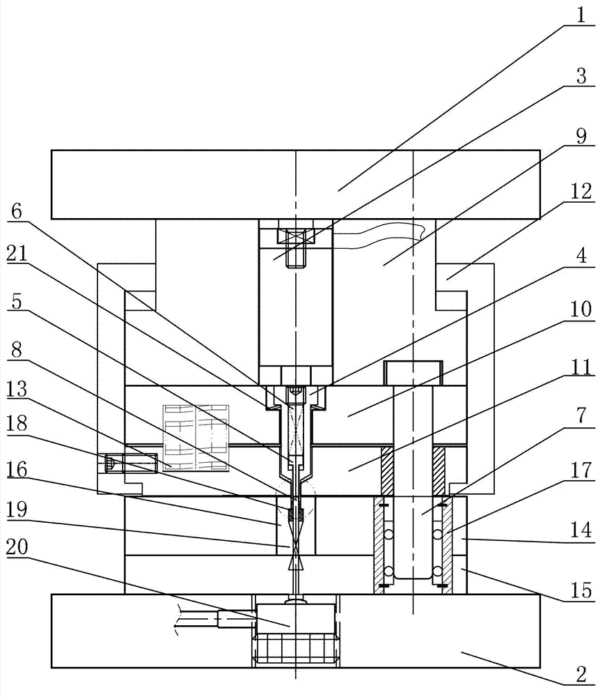
[0015] Specific implementation mode one: combine figure 1 Describe this embodiment, the high-frequency vibration assisted foil plate micro-drawing forming device in this embodiment includes an upper mold base 1, a lower mold base 2, a magnetic telescopic micro-driver 3, a punch 4, a back pressure ejector rod 5, a back pressure Spring 6, guide post 7, drawing punch 8, butterfly spring 21, upper die assembly and lower die assembly, upper die holder 1, upper die assembly, lower die assembly, lower die holder 2 from top to bottom The bottom is arranged in sequence, the upper end of the upper mold assembly is connected to the lower surface of the upper mold base 1, the lower end of the lower mold assembly is connected to the upper surface of the lower mold base 2, and the magnetic telescopic micro-driver 3 and punch 4 are arranged from top to bottom Set in the upper mold assembly in turn, the magnetic telescopic micro-driver 3 is connected to the high-frequency power supply, the po...

specific Embodiment approach 2

[0016] Specific implementation mode two: combination figure 1 To illustrate this embodiment, the upper mold assembly of the high-frequency vibration assisted foil plate micro-drawing forming device in this embodiment includes an upper mold plate 9, an upper mold fixing plate 10, a blanking blank holder 11 and a spacer sleeve 12. The template 9, the upper mold fixing plate 10, and the blanking blank holder 11 are sequentially arranged in the spacer sleeve 12 from top to bottom, and the upper end of the upper template 9 is connected with the lower surface of the upper mold base 1.

[0017] The technical effect of this embodiment is: the limit sleeve 12 has a limit effect on the internal structure of the mould, ensuring a good cooperation between the internal structures of the mould.

[0018] Other components and connections are the same as those in the first embodiment.

specific Embodiment approach 3

[0019] Specific implementation mode three: combination figure 1 To illustrate this embodiment, the upper mold assembly of the high-frequency vibration assisted foil plate micro-drawing forming device in this embodiment also includes a first edge-holding spring 13, and the first edge-holding spring 13 is arranged on the upper mold fixing plate 10 and the falling plate. Between the binder ring 11.

[0020] The technical effect of this embodiment is: the blank-holding spring 13 can ensure a blank-holding effect on the material in the stage of blanking the disc, ensuring smooth blanking of the ring.

[0021] Other components and connections are the same as those in the second embodiment.


PUM


Abstract

The invention relates to a device and a method for micro-deep drawing forming of foil boards, in particular to a method and a device for high-frequency vibration assisted micro-deep drawing forming of foil boards and aims to solve the problem that low-strength foil boards are difficult to form small-diameter cylinder pieces by means of deep drawing. An upper die base, an upper die component, a lower die component and a lower die base of the device are sequentially arranged from top to bottom, the upper end of the upper die component is connected with the lower surface of the upper die base, the lower end of the lower die component is connected with the upper surface of the lower die seat, a magnetic extendable micro-actuator and a male die are arranged in the upper die component sequentially from top to bottom, the magnetic extendable micro-actuator is connected with a high-frequency power supply, a power output end of the magnetic extendable micro-actuator is connected with the upper end of the male die, a back pressure spring and a back pressure ejector rod are arranged in a cavity of the male die sequentially from top to bottom, a deep drawing punch is inserted on the upper surface of the lower die component, and a belleville spring is sleeved on the outer side wall of the upper end of the male die. The device and the method are used for micro-deep drawing forming of the foil boards.

Description

technical field [0001] The invention relates to a foil plate micro-deep-drawing forming device and method, in particular to a high-frequency vibration-assisted foil plate micro-deep-drawing forming device and method. Background technique [0002] With the rapid development of microelectronics technology and microsystem technology, the demand for tiny components of foil plate is increasing day by day, among which the more representative one is the micro cylindrical parts, which are widely used as packages and containers. However, affected by the frictional size effect, the frictional force on the foil plate increases significantly with the decrease of the component size during the deep drawing process, and the foil plate ruptures due to local obvious thinning, and the ultimate drawing ratio ( The ratio of the diameter of the foil plate to the diameter of the cylinder) is small, which limits its application range. In recent years, the demand for cylindrical parts of metals wi...

Claims


Application Information

Patent Timeline
Patent Type & Authority Applications(China)
IPC IPC(8): B21D33/00B21D37/10
Inventor 王春举单德彬郭斌徐杰皇韶峰
Owner HARBIN INST OF TECH
Why Eureka
Try Eureka