Dent adjusting device of dent splitting machine

A technology of adjusting device and slitting machine, which is applied in the direction of mechanical processing/deformation, etc., can solve the problems of large adjustment and alignment error of indentation line, difficult control of indentation depth, and large volume of the whole machine, so as to achieve easy indentation depth, The crimping process is smooth and the effect of small size

Inactive Publication Date: 2013-04-17
QINGDAO JINYE PRECISION MACHINERY
View PDF6 Cites 9 Cited by
  • Summary
  • Abstract
  • Description
  • Claims
  • Application Information

AI Technical Summary

Problems solved by technology

[0003] The present invention solves the problem that the existing indentation slitting machine needs independent mechanisms to complete the pre-pressing and real-pressing respectively, the indentation line adjustment and alignment error of pre-pressing and real-pressing is large, the whole machine is large in size and complex in structure, and it is difficult to control the indentation depth , the technical problem of low control precision, to provide a pre-crimping wheel and the upper crimping wheel on the same part, the alignment error of the indentation line of pre-pressing and real pressing is small, the whole machine is small in size, simple in structure, and easy to control the pressing The indentation adjustment device of the indentation slitting machine with high control precision

Method used


Image

  • Dent adjusting device of dent splitting machine
  • Dent adjusting device of dent splitting machine
  • Dent adjusting device of dent splitting machine

Examples


Embodiment Construction

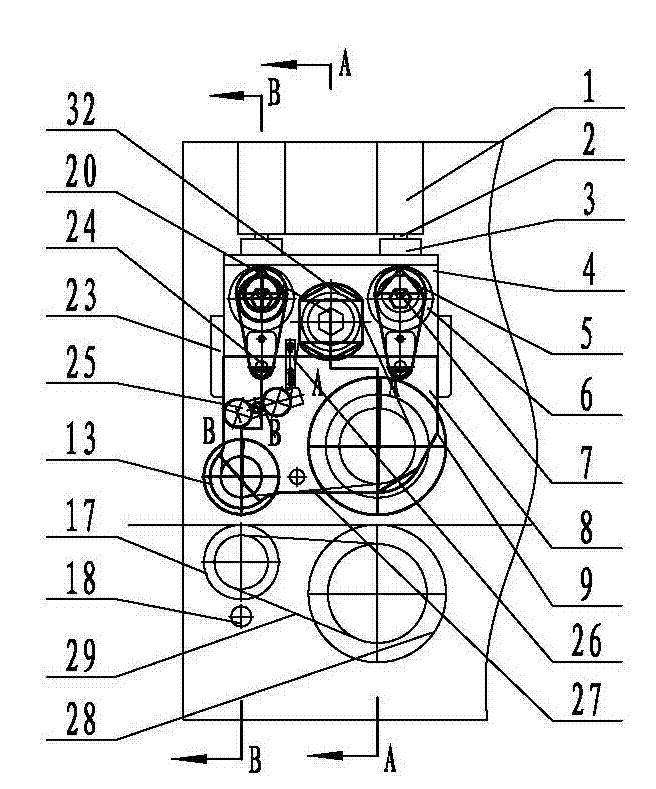
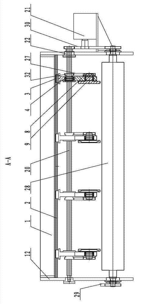
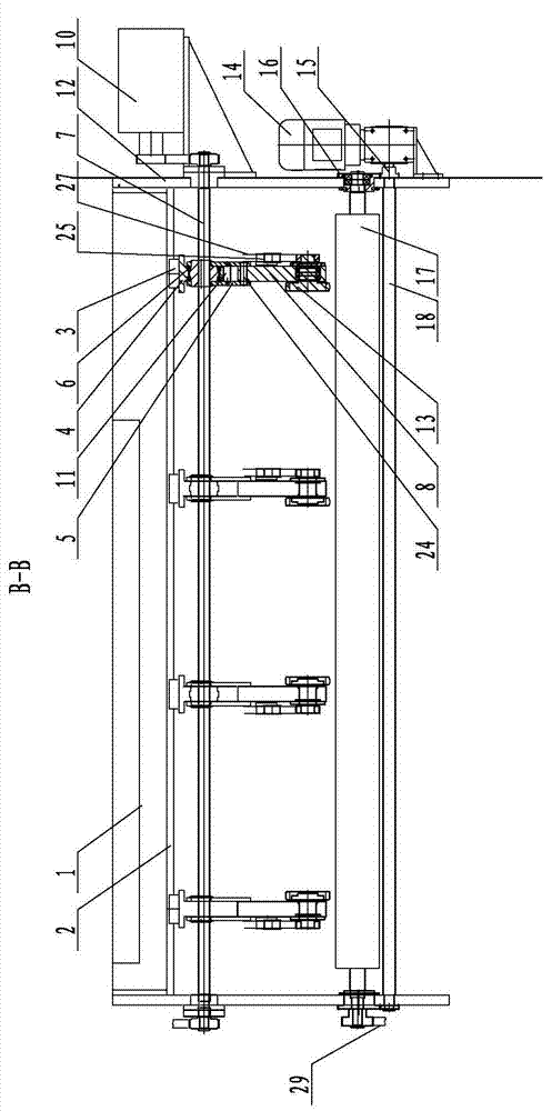
[0019] The first embodiment, combined with Figure 1 to Figure 3 illustrate. For the sake of clarity, figure 1 The wall panel 12 on one side is removed.

[0020] As shown in the figure, the first embodiment is a group of single crimping devices with four sets of crimping parts, as follows figure 2 with image 3 Take the set on the right as an example. The guide rail beam 1 is horizontally fixedly installed between the vertical wall panels 12 on the left and right sides, and the linear guide rail 2 is located below the guide rail beam 1 . A slider 3 is fixed on the upper plane of the fixed plate 4, and the slider 3 is slidingly matched with the linear guide rail 2 in the horizontal direction. The vertical side of the fixed plate perpendicular to the axis of the linear guide rail is parallel to the wall panel 12 . The power driving wheel 32 is installed in the power driving wheel mounting hole on the vertical center line of the vertical side of the fixed plate by a bearin...


PUM


Abstract

The invention relates to a dent device of a paper cutting machine and discloses a dent adjusting device of a dent splitting machine. The dent adjusting device is used for the dent depth adjustment of the dent splitting machine. A power drive wheel is installed on a fixed plate, the inner hole and a power shaft are matched in a sliding mode in the horizontal axial direction, the power shaft drives the power drive wheel to rotate, an eccentric sleeve is installed on the fixed plate, the inner hole and an adjusting shaft are matched in a sliding mode in the horizontal axial direction, the adjusting shaft drives the eccentric sleeve to rotate, a pre-line pressing roller and an upper line pressing roller are installed on a moving plate, the power drive wheel drives the pre-line pressing roller and the upper line pressing roller to rotate in the same direction, a connecting member and an outer circle of the eccentric sleeve are matched in a sliding mode, the connecting member and the moving plate are hinged through a hinge shaft, and parallel sides of a stopping plate and the moving plate are matched in a sliding mode in the vertical direction. The technical problems that a prior slitting mechanism requires independent mechanisms to complete pre-pressing and pressing, the aligning error of dents of pre-pressing and pressing is large, the whole machine is large in volume and complex in structure, the control for dent depths is difficult, and the control accuracy is low are solved.

Description

technical field [0001] The invention relates to an indentation device of a paper cutting machine, in particular to an indentation adjustment device of an indentation slitting machine. Background technique [0002] At present, the indentation adjustment device of the indentation slitting machine usually only has solid pressure and no pre-compression. Due to the difference in thickness and hardness of the cardboard, some layers may break or even the cardboard will be completely broken if it is directly pressed without pre-compression. , the scrap rate is high. The industry lacks attention and in-depth research on pre-pressing. Even if pre-pressing is used in some creasing and slitting machines, it is technically immature. China Utility Model Patent Authorization Announcement No. CN 201800271 U "A Crimping Wheel Assembly Swing Mechanism for a Slitting Machine" discloses a worm gear motor that is controlled and adjusted by an encoder to drive the beam to rotate through the dri...

Claims


Application Information

Patent Timeline
Patent Type & Authority Applications(China)
IPC IPC(8): B31F1/07
Inventor 宋宝三李媛媛周淼
Owner QINGDAO JINYE PRECISION MACHINERY
Why Eureka
Try Eureka