Variable pressure angle cam contour line design method applicable to sudden variable load

A cam profile, cam profile technology, applied in the direction of cams, mechanical equipment, components with teeth, etc., can solve the problems of mismatching and unsuitable load characteristics, and achieve the effect of improving service life, convenient processing and reducing weight

Active Publication Date: 2013-04-17
CENT SOUTH UNIV
View PDF4 Cites 12 Cited by
  • Summary
  • Abstract
  • Description
  • Claims
  • Application Information

AI Technical Summary

Problems solved by technology

The change law of the pressure angle of the cam lift curve does not match the load characteristics, and it is not suitable for the pressure angle requirements under the opening law of the water valve. Therefore, the existing profile curve is not suitable for such heavy-load transient occasions.

Method used


Image

  • Variable pressure angle cam contour line design method applicable to sudden variable load
  • Variable pressure angle cam contour line design method applicable to sudden variable load
  • Variable pressure angle cam contour line design method applicable to sudden variable load

Examples


Embodiment 1

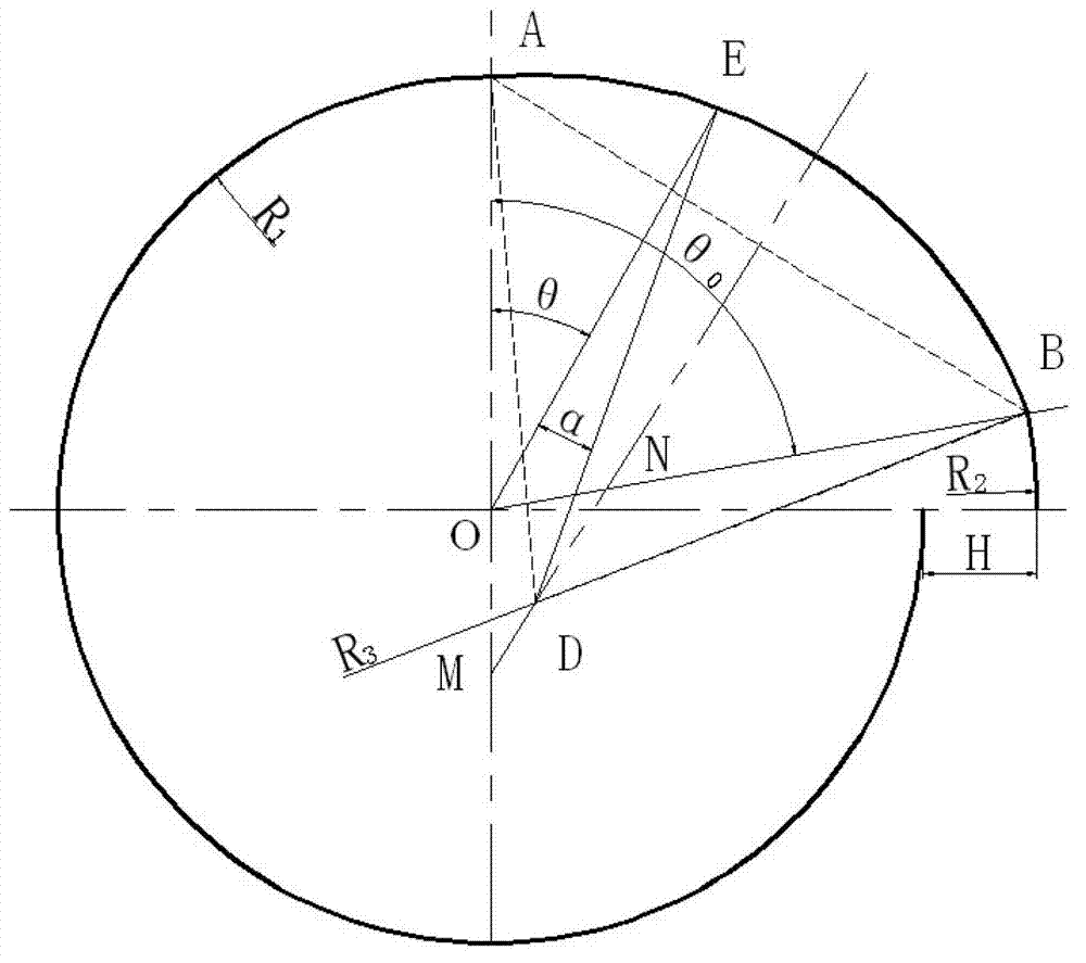
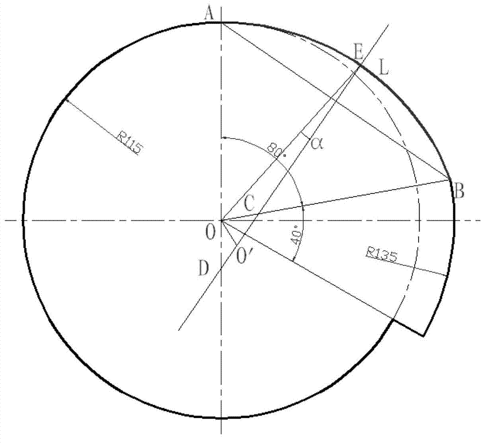
[0043] Taking the cam profile curve design of a 60MN free forging hydraulic press as an example, the minimum radius of the cam is 100mm, and the radius of the roller is 15mm. The lift angle is 80°, the far repose angle is 40°, the gap between the ejector rod and the valve stem is 3-5mm, and the lift is 20mm. The calculation method is as follows. Cam theoretical working curve such as figure 2shown. The lift curve is arc segment AB, where the coordinates of point A are (0,115), and the coordinates of point B are (135cos80°, 135sin80°). So we can know the expression of the perpendicular line L of the straight line AB, that is, the center O' of the arc AB is on the straight line L. In order to satisfy the requirement that the minimum radius of the cam is 115mm and the maximum radius is 135mm, the center of the circle actually moves in the CD segment. Among them, point C is the intersection point of OB, and point D is the intersection point of the extension line of AO. If the ...


PUM


Abstract

The invention discloses a variable pressure angle cam contour line design method applicable to sudden variable load. R1 refers to the radius of a base circle omicron, R2 refers to the farthest dwell arc radius, AB arc refers to a cam contour line with the radius of R3, and alpha refers to a theoretical working curve pressure angle. When the normal values R1 and R2 are given, a graph of relation between a lift range h and the pressure angle alpha can be determined under different R3 values. An optimal arc radius value R3 corresponding to the pressure angle alpha changed along with the lift range h under sudden variable load can be found through the graph. The variable pressure angle cam contour line design method applicable to sudden variable load has the advantages that the pressure angle is extremely small in an open stage of a main valve core during opening of a cam and matched with characteristics of loads, and additional force applied to a top rod can be decreased.

Description

technical field [0001] The invention relates to a variable pressure angle cam profile suitable for sudden heavy loads and a design method. Background technique [0002] The lift valve opening device of the large hydraulic press uses the gear rack and the cam ejector rod as the transmission device to drive the opening and closing of the lift valve spool, thereby realizing the control of the position and speed of the movable beam of the hydraulic press. This type of lift valve opening device has been successfully applied to my country's largest die forging hydraulic press 300MN hydraulic press and other large hydraulic presses, with high control precision and good stability. [0003] Field application shows that the opening driving force of the poppet valve core is huge, up to about 60KN, and the load has the characteristics of transient. A large transient load appears at the moment when the poppet valve is just opened, and then decreases rapidly. In the early stage of water ...

Claims


Application Information

Patent Timeline
Patent Type & Authority Applications(China)
IPC IPC(8): F16H53/02
Inventor 谭建平陈玲杨俊
Owner CENT SOUTH UNIV
Why Eureka
Try Eureka